
Operating
Daily Operating Checklist
o Remove grass and debris from engine compartment and muffler area, before and after operating machine.
o Check area below machine for leaks.
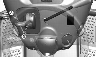
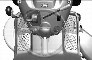
Adjusting Seat
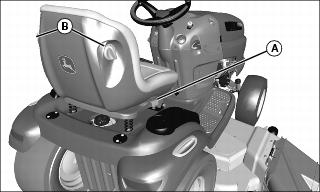
2. Lift up on seat adjustment lever (A) on right side of seat.
3. Lean forward and slide seat forward or rearward to desired position. Do not lean back on top of seat to push rearward.
4. Release seat adjustment lever to lock in position.
Lumbar Seat Adjustment (Models 155C and 190C)
· Turn lumbar seat adjustment dials (B) on either side of seat to adjust firmness of seat.
Adjusting Cutting Height
Cutting height can be adjusted from approximately 25 - 100 mm (1 - 4 in.). When mower deck is in transport position, cutting height is approximately 100 mm (4 in.).
1. Put attachment lift lever into the slot adjacent to desired cutting height.
· Slide the height reminder tab to the desired cutting height for the next time you mow.
Transporting or Getting On and Off Machine
· Pull attachment lift lever all the way back to transport position or 100 mm (4 in.) cutting height.
Checking Mower Deck Level
NOTE: Mower deck wheels should not contact the ground when leveling the mower deck.
1. Park machine safely. (See Parking Safely in the SAFETY section.)
2. Inflate tires to the correct pressure.
3. Move mower lift handle to preferred cutting height.
4. Measure mower deck level (side-to-side).
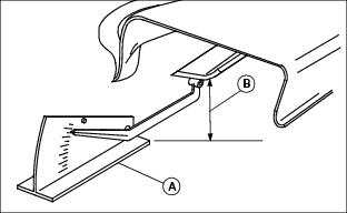
Picture Note: A convenient leveling gauge (A) (AM130907) is available from your dealer.
a. Position mower blades as follows and measure from each outside blade tip (B) to the level surface.
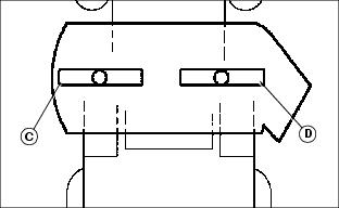
b. Turn left blade (C) as shown. Hold drive belt and turn right blade (D) as shown. Take measurement for both blades.
The difference between blade measurements must not be more than 3 mm (1/8 in.).
c. Adjust mower deck level, if necessary.
5. Measure mower level (front-to-rear).
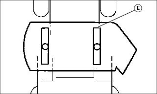
a. Turn right blade (E) so blade tip points straight forward.
b. Measure from blade tip to the surface. Take measurement for both blades.
The front blade tip must be 3-6 mm (1/8 -1/4 in.) lower than rear blade tip.
c. Adjust mower deck level if necessary.
Adjusting Mower Deck Level
NOTE: Mower deck wheels should not contact the ground when leveling the mower deck.
Method One
1. Make sure machine is on a flat, level surface.
2. Check that tires are inflated to correct tire pressure. Tire pressure is marked on the side of the tire.
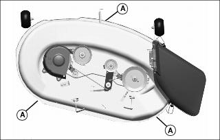
Picture Note: 107 cm (42 in.) mower deck shown
3. Place three short 51 mm (2 in.) blocks of wood under the edges (A) of the mower deck.
4. Lower mower deck to the 65 mm (2.5 in.) cutting height position.
5. Check that the mower deck is level and lightly touching each of the three wooden blocks.
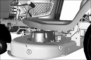
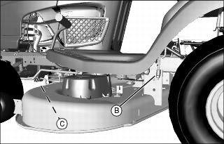
· If the rear of the mower deck is not touching the rear blocks, or is sitting heavily on the blocks, adjust the rear lift links by turning the leveling nut (B) on each lift link. The blocks should be able to easily slide in and out beneath the mower deck when the mower deck is correctly adjusted.
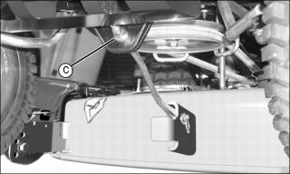
· If the front of the mower deck is not lightly touching the front block, adjust the front draft arm by turning the nut (C).
6. Raise the cutting height to the next hightest position and remove the three wooden blocks.
7. Turn the nut (C) on the front draft arm counterclockwise 1-2 full turns so that the front of the deck is 3-6 mm (1/8-1/4 in.) lower than the rear. This adjustment prevents "double cutting," which wastes horsepower and causes brown grass tips.
Method Two
1. Make sure machine is on a flat, level surface.
2. Check that tires are inflated to correct tire pressure. Tire pressure is marked on the side of the tire.
3. Lower mower deck to the 50 mm (2 in.) cutting height position.
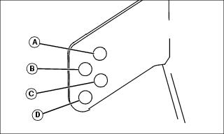
4. With a tape measure or ruler, measure the left rear and right rear edge of the mower deck at points (A). If the two measurements are not equal, turn the leveling nut (B) on each rear lift link to adjust. Repeat procedure until rear corners of the mower deck are level.
5. Measure the front edge of the mower deck directly below the front draft arm hanger at point (A).
· If necessary, turn the front draft arm nut (C) counterclockwise so the front edge of the mower deck is 3-6 mm (1/8-1/4 in.) lower than the rear corners of the mower deck.
NOTE: An optional mower deck leveling gauge (AM130907) is available from your John Deere dealer. It allows for precision mower deck leveling by measuring mower deck level at the blade tips.
Adjusting Mower Deck Wheels
1. Park machine safely. (See Parking Safely in the SAFETY section.)
2. Inflate tires to the correct pressure.
3. Lower mower deck to the desired mowing position.
NOTE: Bottom of wheels should be approximately 3-13 mm (1/8-1/2 in.) from the ground.
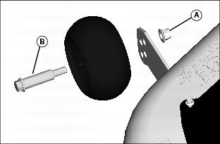
4. Check each mower wheel position. Remove nut (A) and bolt (B), and move mower wheel to proper hole.
5. Install bolts and nuts to lock wheels in position. Tighten nuts to 34 N·m (25 lb-ft).
Testing Safety Systems
The safety systems installed on your machine should be checked before each machine use. Be sure you have read the machine operator manual and are completely familiar with the operation of the machine before performing these safety system checks.
Use the following checkout procedures to check for normal operation of machine.
If there is a malfunction during one of these procedures, do not operate machine. See your authorized dealer for service.
Perform these tests in a clear open area. Keep bystanders away.
Testing Park Brake Switch
1. Park machine safely. (See Parking Safely in the SAFETY Section.)
Testing Park Brake
1. Park machine safely. (See Parking Safely in the SAFETY Section.)
3. Put transmission in neutral. Engage free-wheeling lever on units with an automatic transmission.
4. Try to push machine manually.
Testing Attachment Engagement Switch or Lever
1. Park machine safely. (See Parking Safely in the SAFETY Section.)
· On models with electric attachment engagement switch, pull switch up.
· On models with mechanical attachment engagement lever, push lever forward.
Testing Seat Switch
1. Park machine safely. (See Parking Safely in the SAFETY Section.)
b. Move throttle lever up to maximum engine speed.
c. Unlock park brake and release brake pedal.
e. Raise up off seat. Do not get off machine.
c. Unlock park brake and release brake pedal.
d. Raise up off seat. Do not get off machine.
d. Raise up off seat. Do not get off machine.
Testing Reverse Implement Option (RIO)
1. Park machine safely. (See Parking Safely in the SAFETY section.)
3. Engage attachment engagement switch or lever to start attachment.
Before backing up, carefully check the area around the machine. |
4. Look behind the vehicle to be sure there are no bystanders.
5. Begin reverse travel by depressing reverse foot pedal for automatic transmission or moving gear shift lever to R (reverse) position for gear transmission.
Using the Park Brake
Always lock the park brake and remove the key before leaving the machine unattended. |
Locking park brake:
1. Push and hold brake pedal down.
2. Pull park brake lever up to lock park brake.
3. Release brake pedal. Pedal should stay down and park brake lever should stay locked.
Unlocking park brake:
1. Push and hold brake pedal down.
2. Push park brake lever down to unlock park brake.
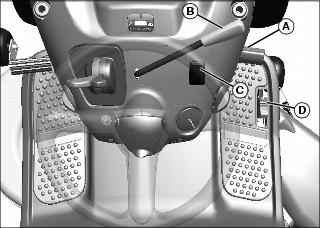
Using the Hour Meter and Service Reminder (Models 125, 135, 145, 155C and 190C)
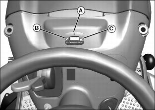
· The hour meter (A) shows the number of hours the engine has run. The service reminder will indicate that a general lubrication (B) or mower/engine (C) service interval has been reached. When service is required, the service reminder will flash for one hour. Follow the service timetable on the maintenance schedule located under the seat. For specific service procedures, see the Service section of this manual.
· Turn the key to STOP position when not using the machine.
Using Key Switch and Headlights
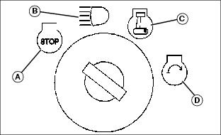
Engine Off
NOTE: Headlights will drain the battery rapidly if key switch is left in headlights on position (B) with the engine off.
· To turn headlights on, turn key switch to headlights on position (B).
· To turn headlights off, turn key switch to STOP position (A).
Engine On
· To turn headlights on, start engine, then turn key switch from run position (C) to headlights on position (B).
· To turn headlights off, turn key switch from headlights on position (B) to run position (C).
Starting the Engine
1. On automatic models: Make sure free-wheeling lever is pushed in.
3. Make sure mower is disengaged. (See Engaging and Disengaging Mower in the OPERATING section.)
5. For gear models, put transmission in neutral.
· On Models 125, 135, 145, 155C and 190C, move throttle lever (A) to the half-speed position and move choke lever (B) up to the choke position.
· On models 102 and 115, move throttle/choke lever (C) up to the choke position.
· If engine is warm: Move throttle or throttle/choke lever to the half-speed position.
IMPORTANT: Avoid damage! Starter may be damaged if starter is operated for more than 20 seconds at a time: · Wait two minutes before trying again if engine does not start. |
7. Turn key to start position for no more than five seconds.
8. Release key to run position when engine starts and on models 125, 135, 145, 155C and 190C, gradually move choke lever down to the off position.
· If engine does not start, wait 10 seconds.
· Turn key to start position again for no longer than 5 seconds.
· Repeat procedure if necessary.
IMPORTANT: Avoid damage! Unnecessary engine idling can cause engine overheating, carbon build-up, and poor performance. |
9. Let engine run at half-speed position for a couple of minutes to warm-up before operating machine.
Idling the Engine
· Engine is air cooled and needs a large volume of air to keep cool. Keep air intake screen on top of engine clean.
· Keep hood closed when engine is idling.
Stopping the Engine
IMPORTANT: Avoid damage! Do not stop the engine by moving choke control to the choke position. Backfire, fire or engine damage can occur. Follow recommended procedure for stopping engine. |
1. Let engine run at high throttle without load for a few seconds.
2. Turn key to STOP position. Engine will stop and headlights will turn off.
Using Travel Controls on Gear Transmission
IMPORTANT: Avoid damage! Stop machine movement before shifting between reverse and forward to prevent transmission damage. |
Travel Forward
1. Push brake/clutch pedal (A) all the way down to stop machine.
2. Move transmission shift lever (B) to desired travel speed.
3. Release brake/clutch pedal slowly.
Travel in Reverse
1. Push brake/clutch pedal (A) all the way down.
NOTE: Any operating attachment and the engine will stop as the gear shift lever is moved to R (reverse) with attachment engaged.
2. Pull attachment engagement lever (C) back to the off position to disengage attachment.
3. Look behind the machine to be sure there are no bystanders nearby.
4. Move shift lever (B) to R (reverse) position (D).
5. Release brake/clutch pedal slowly.
Emergency Stopping
Using Travel Controls on Automatic Transmission
Travel Forward
· Push down the forward travel pedal (A).
Travel in Reverse
NOTE: Any operating attachment and the engine will stop as the reverse foot pedal is pressed with attachment engaged.
· On models with mechanical attachment engagement lever, pull lever (B) back to the off position.
· On models with electric attachment engagement switch, push switch in location (C) (not shown above) down to the off position.
2. Look behind the machine to be sure there are no bystanders nearby.
3. Touch the reverse travel pedal (D) with front of foot and slide foot over pedal from front to rear.
Emergency Stopping
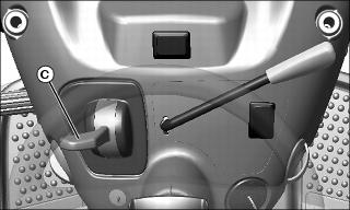
Using The Reverse Implement Option (RIO)
Before backing up, carefully check the area around the machine. |
NOTE: Backing up while the mower is engaged is strongly discouraged. The Reverse Implement Option should be used only when operating another attachment or when the operator deems it necessary to reposition the machine with the mower engaged.
2. Look behind the machine to be sure there are no bystanders.
3. Push and hold in the reverse implement switch (A) while depressing reverse foot pedal slightly for automatic transmission or moving the gear shift lever to the R (reverse) position for gear transmission.
NOTE: If the engine and mower stop while repositioning the machine, return the attachment engagement lever/switch to the off position. Start engine and engage mower. Begin again with Step 2.
4. Release the reverse implement switch and reposition the machine as the machine begins to move rearward.
5. Resume forward travel. The mower should continue operating.
6. Repeat procedure to position the machine again.
Using Cruise Control (On Models 125, 135, 145, 155C and 190C)
Use cruise control when you want to maintain travel speed without having to hold the forward travel pedal down. Cruise control operates only for forward travel.
Engage Cruise Control
1. Push forward pedal down until you reach desired travel speed.
2. Pull cruise control lever up and release forward pedal to lock the cruise control.
Disengage Cruise Control
· Depress brake pedal, tap on forward pedal or push cruise control lever down to the off position.
Engaging and Disengaging Mower
NOTE: Put attachment lift lever in transport position to transport machine or when parking machine.
1. Start engine and run at half speed for a couple of minutes to warm up.
2. Lower mower deck to desired cutting height position.
NOTE: Throttle lever should be at full throttle position before engaging mower to avoid stalling engine.
3. Push throttle lever up to the full throttle position.
· On models with electric attachment engagement switch: Pull switch up.
· On models with mechanical attachment engagement lever: Push lever forward.
NOTE: The mower and engine will stop as the reverse foot pedal is pressed for Automatic Transmission or when the gear shift lever is moved to the R (reverse) position for Gear Transmission with mower engaged.
5. Disengage mower blades before moving in reverse or stopping engine.
· Machines with mechanical attachment engagement lever: Pull lever back.
· Machines with electric attachment engagement switch: Push switch down.
Using Mulch Cover (107 cm (42 in.) and 122 cm (48 in.) Mower Decks
NOTE: Remove mulch cover for side discharge operation.
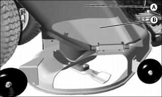
Picture Note: 122 cm (48 in.) used for illustration.
1. Raise discharge chute (A) and metal deflector (B).
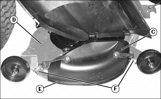
2. Install mulch cover (C) onto mower deck (D). Mulch cover lip (E) must be seated in mower deck groove.
3. Hook mulch cover to mower deck:
· On 122 cm (48 in.) deck, wheel bracket grooves (F).
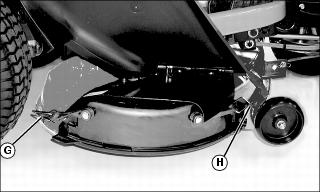
· On 107 cm (42 in.) deck, slot (G) on left side and wheel bracket hole (H).
4. Lower discharge chute and metal deflector.
5. Make sure bagger blades are not installed for maximum mulching operation.
Unplugging Mower, Bagger, or Material Collection System
Checking For Plugging While Driving
Check the flow indicator on MCS chute (if equipped) periodically for any indication of loss of air flow.
If grass builds up in front of mower discharge chute, check for plugged chute or problems with blower assembly (if equipped).
If there is a trail of clippings behind mower or clippings blow to the side, check for plugged chute, full collector bags, or problems with blower assembly.
Removing Debris From Inspection Points:
1. Park machine safely. Wait for all moving parts to stop before getting off to inspect machine.
2. Open hopper cover. Check chute outlet.
3. Remove chute from mower deck or blower assembly. Check chute inlet.
4. Check under mower deck for debris.
Pushing Machine
IMPORTANT: Avoid damage! Transmission damage may occur if the machine is towed or moved incorrectly: |
2. Put transmission in N (neutral).
3. On Automatic Models: Pull out on free-wheeling lever (A).
4. Push machine to desired location.
5. On Automatic Models: Push free-wheeling lever back in.
Transporting Machine on Trailer
NOTE: Trailer capacity must exceed combined machine weight and attachment weight. (See Specifications section in operator's manual).
Be sure trailer has all the necessary lights and signs required by law.
1. Park trailer on level surface.
2. Raise mower deck, if installed, before driving machine onto trailer.
3. Drive machine onto heavy-duty trailer. Position machine on trailer so hood or engine cover will not raise in wind while being transported.
4. Lower mower deck completely.
6. Turn off machine and remove key.
7. Fasten machine at the axle or frame to trailer with heavy-duty straps, chains, or cables. Both front and rear straps must be directed down and outward from machine.
8. Secure hood to prevent from lifting while driving.
Using Weights
Use weights to improve stability when operating on slopes or using attachments. |
NOTE: See your authorized dealer for recommended weights.
· Install front weights for added stability and steering control when you use equipment such as the rear-mounted grass bagger.
· Install rear weights when using the snow blade or snowblower.
· Remove weights when not required.
Using Tire Chains
Tire chains are recommended for use with most front attachments. Remove tire chains before installing mower deck.
See your attachment Operator's Manual for tire chain recommendation. See your authorized dealer for the chains.
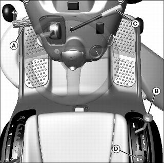
Using Accessories
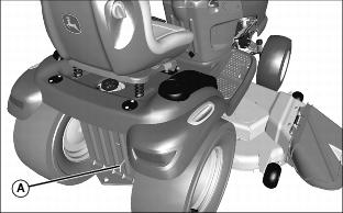
Using the Power Port (If Equipped)
An electric power port (A) can be used for accessories. See your authorized dealer.
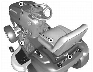
Using CargO Mount System
The front and rear CargO Mount System brackets (B) can be used for easy attachment of selected optional equipment.
Use John Deere approved optional equipment only. See your Authorized Service Center for approved optional equipment.
Using Storage Accessories
· Use the storage pocket (C) for small items such as gloves.
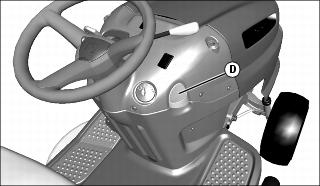
· On Models Without Cruise Control: Use the storage retainer (D) to hold items such as a garage door opener.
Mowing Tips
The following recommendations will produce the best lawn cut quality and appearance:
· Keep mower blades sharp. Dull blades will tear grass; tips of grass will then turn brown.
· Cutting grass too short may kill grass and let weeds grow easily. The suggested finished cut height range is 44 - 70 mm (1.75 - 2.75 in.).
· Adjust cutting height to remove only 1/3 of the grass at a time.
· Mow grass often. Short grass clippings will decay quickly.
· Mow with engine at full throttle.
· Adjust travel speed to match mowing conditions:
· Travel at slow speed when you mow thick, tall grass, make sharp turns or trim around objects.
· Travel at moderate speed when you mow thin grass.
· Use a different mowing pattern each time you mow. Overlap mowing paths 50 - 100 mm (2 - 4 in.).
· Drive over ridges and through shallow ditches straight-on, not at an angle.
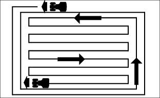
· Mow around the outside twice, then mow inside in straight passes. Best cut is achieved when mowing in a straight line.
· When mowing or mulching near pavement, overlap the pavement by 50 mm (2 in.) to allow clippings to dispense over grass.
· A thick layer of mulched leaves can prevent sunlight from getting to grass and smother it. Taller grass heights allow mulched leaves to dispense easier in lawn. Mulch leaves several times if needed.
· Use a thatcher in late spring or summer to pull up dead grass and aerate ground.
· For Mulching Mower: Shorter cut heights will provide better cut quality, but may leave noticeable clippings. Higher cut heights will reduce clippings, but cut quality may decline.