
Operating
Daily Operating Checklist
o Check transmission oil level.
o Check coolant level on liquid cooled engine.
o Remove grass and debris from engine compartment and muffler area, before and after operating machine.
o Check area below machine for leaks.
o Check operation of backup lights.
Avoid Damage to Plastic and Painted Surfaces
· Do not wipe plastic parts unless rinsed first.
· Insect repellent spray may damage plastic and painted surfaces. Do not spray insect repellent near machine.
· Be careful not to spill fuel on machine. Fuel may damage surface. Wipe up spilled fuel immediately.
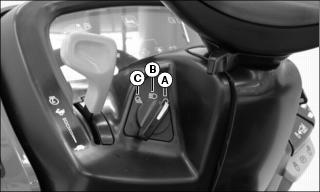
Operator Station Controls
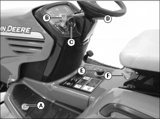
C - Power-Take-Off (PTO) / Reverse Implement Option (RIO) Switch
Miscellaneous Controls
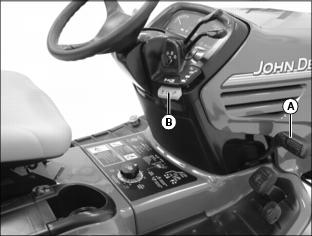
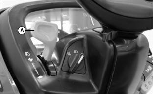
Adjusting Tilt Steering Wheel
1. Move tilt steering lever (A) rearward.
2. Push or pull steering wheel to a comfortable operating position.
4. Check to be sure steering wheel is locked in position.
Adjusting Seat
Adjusting Seat Position
1. Move seat adjustment lever (A) to the left.
2. Slide seat forward or backward to desired position.
4. Check to be sure seat is locked in position.
Adjusting Seat Height
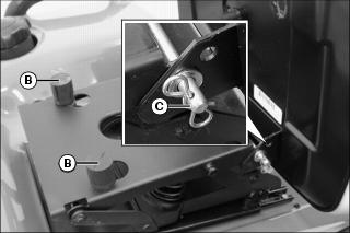
Rubber stops (B) may be flipped to position at two different heights.
Seat rod (C) may be positioned at three different heights.
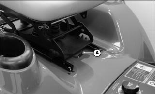
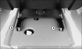
Positioning Slide Rails

1. Remove two bolts (A) in rear of slide rail.
2. Loosen two bolts (B) in front of slide rail.
3. Slide rails with seat and suspension forward one inch to mounting holes (C).
4. Install four bolts in slide rail.
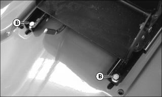
Positioning Seat and Suspension
1. Disconnect seat wire harness and remove seat.
2. Remove two bolts (A) in rear of slide rail.

3. Remove two bolts (B) in front of slide rail.
4. Remove seat suspension and slide rails from machine.
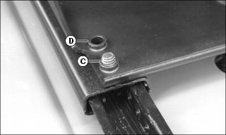
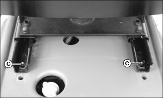
5. Remove four bolts (C) securing seat suspension to slide rails.
6. Move slide rails and install bolts in forward mounting holes (D).
7. Install seat suspension and slide rails on machine with four bolts.
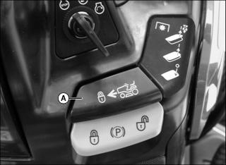
Using Mower Height Control Knob
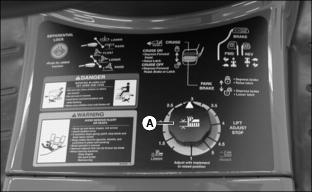
Use mower height control knob (A) to adjust mower cutting height, and lock mower deck lift arms in raised position. See your mower deck operator's manual for instructions.
Testing Safety Systems
Use the following checkout procedure to check for normal operation of machine.
If there is a malfunction during one of these procedures, do not operate machine. See your John Deere dealer for service.
Perform these tests in a clear open area. Keep bystanders away.
Testing PTO/RIO Switch
Test 1:
1. Depress brake pedal, or lock park brake.
2. Pull PTO/RIO switch up to engage PTO.
Test 2:
2. Unlock park brake and release brake pedal.
3. Move throttle lever up to maximum engine speed.
4. Pull PTO/RIO switch up to engage PTO.
Testing Seat Switch
Test 1:
2. Move throttle lever up to maximum engine speed.
3. Unlock park brake and release brake pedal.
4. Pull PTO/RIO switch up to engage PTO.
5. Raise up off seat. Do not get off machine.
Test 2:
3. Unlock park brake and release brake pedal.
4. Raise up off seat. Do not get off machine.
Testing Park Brake Switch
Test 1:
1. Unlock park brake and release brake pedal.
Test 2:
4. Raise up off seat. Do not get off machine.
Testing Reverse Implement Option (RIO)
Before backing up, carefully check the area around the machine. |
2. Move throttle lever up to maximum engine speed.
3. Engage PTO to start attachment.
4. Look behind machine to be sure there are no bystanders.
5. Begin reverse travel by depressing reverse travel pedal.
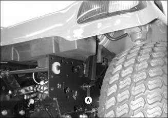
Using Fuel Shut-Off Valve
Close valve when performing engine service, during machine transport and during storage.
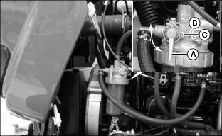
Picture Note: Fuel shut-off valve shown in open position
2. Open or close fuel shut-off valve lever (A) as required:
· Open valve: Rotate valve lever to "O" (vertical) position (B).
· Close valve: Rotate valve lever to "C" (horizontal) position (C).
Using Park Brake
Locking Park Brake
Always lock the park brake and remove the key before leaving the machine unattended. |
1. Fully depress brake pedal (A).
2. Pull park brake latch (B) up to lock park brake.
3. Release brake pedal and then park brake latch. Pedal should stay down and park brake latch should stay up in locked position.
Unlocking Park Brake
2. Push park brake latch down.
3. Release brake pedal. Pedal should come up to operating position.
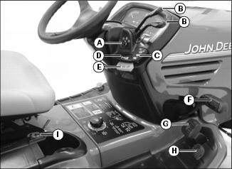
Using Key Switch
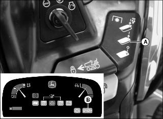
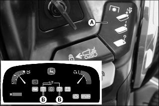
Using Indicator Lights
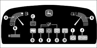
A - Fuel Gauge - indicates fuel level.
B - Hour Meter - shows number of hours engine has run. Check hour meter daily, and see periodic service required chart located under hood for service requirements.
C - Engine Preheat/Overheat Indicator Light - will come on for up to 8 seconds when starting engine. If engine has been run and then cooled, the time may be less. If engine has been run and is hot, the light will not come on.
This light will also come on when needle on temperature gauge is in red range.
D - Service Indicator Light - will come on after first 50 hours of operation, and continue to come on at 200 hour intervals when periodic service is required.
See hour meter reading, and periodic service required chart located under hood for service requirements when light comes on.
NOTE: Service indicator light must be reset each time service is performed.
E and G - PTO Indicator Lights - will come on when mid/front and/or rear PTO is engaged.
F - Oil Pressure Indicator Light - will come on when engine oil pressure is too low. If indicator comes on during operation, stop engine and perform appropriate service. This is an indication that the engine is low on oil.
H - Battery Discharge Indicator Light - will come on when there is no alternator output. If indicator comes on during operation, stop engine and perform appropriate service.
I - Air Restriction Indicator Light - will come on when air cleaner elements require service.
J - Reverse Implement Option (RIO) Indicator Light - will come on when RIO is engaged.
K - Coolant Temperature Gauge - indicates temperature of cooling system. If needle on gauge reaches red range, the engine is overheating. If PTO is engaged, it will automatically shut off.
If engine is overheated, disengage PTO, let engine cool at idle speed until needle returns to green range. Shut off engine and clean air intake screens and radiator screen.
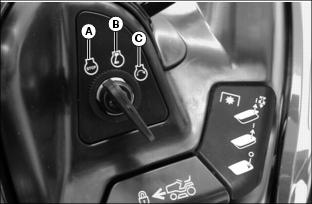
Using Light Switch
B - Headlights and taillights on.
C - Headlights, taillights and rear worklights on.
Starting the Engine
NOTE: You must depress brake pedal, or lock park brake, before you can start engine. Be sure PTO/RIO switch is off.
2. Lock park brake or depress brake pedal.
3. Push throttle lever (A) up to between 1/2 and fast position.
· Service indicator light will be ON.
· Oil pressure indicator light will be ON.
· Battery discharge indicator light will be ON.
· Engine preheat/overheat indicator light will come on and go out within approximately 8 seconds. If engine has been run and then cooled, the time may be less. If engine has been run and is hot, the light will not come on. Wait for indicator to go out before cranking engine.
6. Turn key to start position:
· If engine does not start within 5 seconds, turn key to stop position and wait 10 seconds.
· Crank engine again for 5 seconds.
Repeat this procedure if necessary.
7. As soon as engine starts, release key. The key will return to run position and all indicator lights should be off. If a light does not go off, stop engine and perform appropriate service.
Idling the Engine
NOTE: Allowing engine to idle for long periods of time will waste fuel and cause carbon build-up.
1. Adjust throttle lever to slow idle speed.
Stopping the Engine
2. Pull throttle lever down to the slow position.
3. Turn key to stop (Off) position.
Emergency Stopping
1. Remove foot from forward or reverse travel pedals.
3. Turn key switch to stop (Off) position. Do not release brake pedal until all moving parts have stopped.
4. If possible, lock the park brake.
Using Travel Pedals
Forward Travel
2. Slowly push down forward travel pedal (A). Machine will travel faster the farther down you push the pedal.
3. Release forward pedal, machine will automatically slow down and return to neutral.
Reverse Travel
NOTE: Any operating attachment should stop as the reverse foot pedal is depressed with attachment engaged.
2. Push PTO/RIO switch down to off position to disengage attachment.
3. Look behind machine to be sure there are no bystanders nearby.
4. Slowly push down reverse pedal (B). Machine will travel faster the farther down you push the pedal. Release reverse pedal, machine will automatically slow down and return to neutral.
Stopping
1. Release either travel pedal, machine will automatically slow down and return to neutral.
2. Depress brake pedal (C). Machine brakes will be applied to assist in stopping.
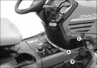
Using Cruise Control
Use cruise control when you want to maintain travel speed without having to hold the forward travel pedal down. Cruise control operates only for forward travel.
Operate machine in a large, open area to learn how cruise control works.
Engaging Cruise Control
1. Depress forward travel pedal until you reach desired travel speed.
2. Pull cruise latch (A) up to lock cruise control.
3. Remove foot from forward travel pedal.
Disengaging Cruise Control
1. Depress forward travel pedal or depress brake pedal.
Using Reverse Implement Option (RIO)
Before backing up, carefully check the area around the machine. |
NOTE: Backing up while mower is engaged is strongly discouraged. The Reverse Implement Option should be used only when operating another attachment or when operator deems it necessary to reposition machine with mower engaged.
1. Stop machine forward travel with attachment engaged.
2. Look behind machine to be sure there are no bystanders.
NOTE: If attachment stops while repositioning machine, return PTO/RIO switch to off position. Begin again with Step 2 in procedure.
3. Lift and hold PTO/RIO switch (A) up past the PTO engagement position to activate the reverse implement option while depressing reverse travel pedal slightly. Instrument panel RIO indicator light (B) will come on when RIO is engaged.
4. As machine begins to move backward, release PTO/RIO switch and reposition machine. Instrument panel RIO indicator light will go out when switch is released.
5. Resume forward travel. The attachment should continue operating.
6. Repeat Steps 1 through 5 to reposition machine again.
Using Differential Lock
IMPORTANT: Avoid damage! To prevent damage to differential, do not engage differential lock at high speeds. |
The differential lock is used to provide better traction when rear wheels start to slip. Do not use differential lock unless you are experiencing rear wheel slippage. Engaging differential lock will cause both rear wheels to drive equally to improve traction.
Engaging Differential Lock
2. Push down on differential lock pedal (A). Lock will remain engaged as long as pedal is depressed.
NOTE: Turning radius is increased when differential is locked.
When brake pedal is depressed, differential lock will automatically engage.
Disengaging Differential Lock
1. Release differential lock pedal.
2. Once the load on the transmission is equalized and reduced, the differential lock will disengage automatically.
Using 12-Volt Outlet
NOTE: Accessory must be rated at 20 amps or less.
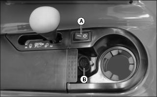
1. Depress bottom of switch (A) to turn power off.
2. Remove 12-volt outlet cover (B) and install accessory cord in outlet.
3. Depress top of switch (A) to power the accessory.
4. Install cover (B) in outlet after use.
Installing Attachments
Attachments can be installed on the front, mid or rear of machine.
An optional front quick hitch and an optional rear 3-point hitch are required for operation of some attachments.
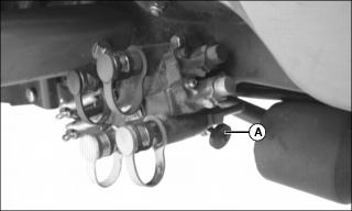
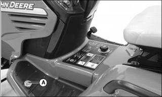
A hydraulic cylinder lockout valve is required for loader operation, and for operation of some attachments mounted on the front quick hitch. Turn knob (A) to close the lockout valve to avoid operation delays, and to restrict movement of mid and rear 3-point hitch mounted attachments.
In addition to the instructions in your attachment operator's manual, perform the following procedures:
Front quick hitch mounted attachments
1. Pull upper hydraulic control lever backward to fully raise mower deck lift arms and fully raise rear 3-point hitch if installed.
2. Turn mower cutting height knob clockwise to highest position to lock mower deck lift arms in raised position.
3. If installed, turn rear 3-point hitch depth control rod clockwise to lock rear 3-point hitch in raised position.
4. If installed, turn hydraulic cylinder lockout valve knob (A) clockwise until closed.
Mid-mounted attachments
1. If installed, disconnect front mounted attachment hydraulic hoses from machine:
· Disconnect front quick hitch angling cylinder hydraulic hoses; or disconnect snowblower or snowthrower chute rotation hoses.
· Install dust caps on hoses and SCV couplers, and secure hoses to attachment or machine.
2. If installed, turn hydraulic cylinder lockout valve knob (A) counterclockwise until fully open.
3. Pull upper hydraulic control lever backward to fully raise rear 3-point hitch if installed. Mower deck lift arms will raise at same time.
4. If installed, turn rear 3-point hitch depth control rod clockwise to lock rear 3-point hitch in raised position.
Rear three-point hitch mounted attachments
1. If installed, disconnect front mounted attachment hydraulic hoses from machine:
· Disconnect front quick hitch angling cylinder hydraulic hoses; or disconnect snowblower or snowthrower chute rotation hoses.
· Install dust caps on hoses and SCV couplers, and secure hoses to attachment or machine.
2. If installed, turn hydraulic cylinder lockout valve knob (A) counterclockwise until fully open.
3. Pull upper hydraulic control lever backward to fully raise mower deck lift arms. Rear 3-point hitch will raise at same time.
4. Turn mower cutting height knob clockwise to highest position to lock mower deck lift arms in raised position.
5. Turn rear 3-point hitch depth control rod to desired height.
Connecting Attachment Hydraulic Hoses
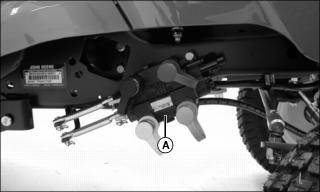
The machine dual Selective Control Valve (SCV) (A) has hydraulic outlets with female quick couplers, color coded for easy hookup.
Attachment hydraulic hoses are also color coded. Match color coded hose ends to color coded couplers on the SCV when making connections.
NOTE: Engine must be off to relieve hydraulic pressure before connecting attachment hoses.
With engine off, relieve hydraulic pressure by moving both hydraulic control levers back-and-forth several times before connecting attachment hydraulic hoses.
IMPORTANT: Avoid damage! To prevent contamination of hydraulic system, color coded dust caps should be installed in couplers and on hose ends when not being used. |
Using Hydraulic Control Levers
NOTE: Hydraulic control levers operate differently depending on attachment. See attachment operator's manual before using hydraulic control levers with an attachment.
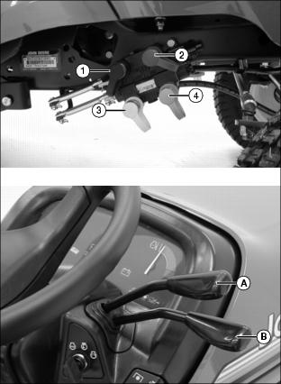
When attachment hydraulic hoses are connected to couplers 1(black) and 2 (green), push lower hydraulic control lever (B) forward to divert fluid to coupler 1 and return through coupler 2. Pull lever backward to divert fluid to coupler 2 and return through coupler 1. Push lever to the full forward or float position to remove pressure in both lines and allow fluid to flow back and forth between lines. Lever should return to neutral position when released.
When attachment hydraulic hoses are connected to couplers 3 (yellow) and 4 (silver), push upper hydraulic control lever (A) forward to divert fluid to coupler 3 and return through coupler 4. Pull lever backward to divert fluid to coupler 4 and return through coupler 3. Lever should return to neutral position when released.
NOTE: When not using lower hydraulic control lever, periodically move lever back and forth to maintain lubrication. Be sure lever is returned to middle (neutral) position and not locked in forward (float) position.
Using the Power-Take-Off (PTO) Safely
Using the PTO (Power-Take-Off)
NOTE: Any operating attachment should stop as the reverse travel pedal or brake pedal is depressed with attachment engaged. Prior to operating the PTO, see Using Reverse Implement Option (RIO) in this section.
This machine is equipped with a 2000 rpm mid PTO.
Always operate engine at maximum speed when PTO is engaged.
Engaging PTO
1. Reduce travel speed or stop machine.
2. After engine has warmed, move throttle lever up to maximum engine speed.
3. Pull PTO/RIO switch (A) up. Instrument panel PTO indicator light(s) (B) will come on when PTO is engaged.
Disengaging PTO
NOTE: If reverse travel pedal or brake pedal is depressed, PTO will disengage.
1. Push PTO/RIO switch down to disengage PTO. Instrument panel PTO indicator light(s) will go out.
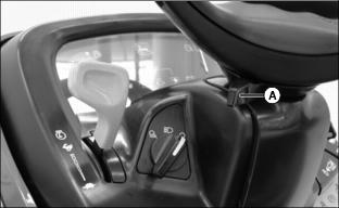
Pushing Machine
IMPORTANT: Avoid damage! Transmission damage may occur if machine is towed or moved incorrectly: |
Use the free-wheeling lever when pushing the machine.
Using Free-Wheeling Lever
When you need to move the machine without starting the engine, use the free-wheeling lever:

2. Pull free-wheeling control lever (A) fully up to open the free-wheeling valve.
4. Push machine to desired location.
Lever will return to lowered position, closing valve when machine is started and driven.
Unplugging Mower or Optional Bagger
· Park the machine safely and lock the park brake before getting off the seat. |
3. Move throttle lever to slow position.
8. Wait for all moving parts to stop.
Transporting Machine on Trailer
NOTE: Trailer capacity must exceed combined machine weight (see Specifications section) and attachment weight.
Be sure trailer has all necessary lights and signs required by law.
IMPORTANT: Avoid damage! Transmission damage may occur if machine is towed or moved incorrectly: |
1. Drive forward onto heavy-duty trailer.
2. Lower mower to trailer deck.
4. Machines with fuel shut-off: Turn fuel shut-off to off position.
5. Fasten machine to trailer with heavy-duty straps, chains, or cables. Both front and rear straps must be directed down and outward from machine.
Ballasting Machine Safely
Determine amount of ballast required for each operation. Ballast used for one operation may be wrong for another. Ballast for stability, steering control and traction.
Use no more ballast than required, and remove ballast when it is no longer needed.
Ballast should be limited by machine and tire capacities. Each tire has a maximum inflation pressure and a maximum load capacity which must not be exceeded.
Additional front ballast may be required for road travel with rear-mounted attachments.
See your attachment operator's manual for ballasting requirements.
Ballasting Machine
Using Front Weights
IMPORTANT: Avoid damage! Do not exceed maximum front ballast of nine Quick-Tatch weights and two wheel weights. |
Two types of front weights are available for your machine, Quick-Tatch weights and wheel weights. Quick-Tatch weights can be mounted on the front bumper, and wheel weights are mounted on the front wheels.
Up to four Quick-Tatch weights can be mounted on the front bumper. Another five weights can be added if you install the optional front weight bracket. Each Quick-Tatch weight is 19kg (42 lb).
One wheel weight can be installed on each front wheel. Each front wheel weight is 14kg (30 lb).
See your John Deere dealer for front weights and kits to best fit your needs.
Using Rear Weights
IMPORTANT: Avoid damage! Do not exceed maximum rear ballast of 385kg (850 lb). Rear ballast includes Quick-Tatch weights, rear wheel weights, weight box, and adding liquid weight to tires. |
Two types of rear weights are available for your machine, Quick-Tatch weights and wheel weights. The Quick-Tatch weights can be mounted on an optional rear weight bracket, and wheel weights are mounted on the rear wheels.
Up to six Quick-Tatch weights can be mounted on the rear weight bracket. Each Quick-Tatch weight is 19kg (42 lb). Use of these weights is required when an attachment, such as a snowthrower or snowblower is used.
Up to three wheel weights can be installed on each rear wheel. Rear wheel weights are available in 23kg (50 lb) and 33kg (72 lb).
See your John Deere dealer for rear weights and kits to best fit your needs.
Follow instructions in this manual for installing rear wheel weights.
Adding Liquid Weight in Tires
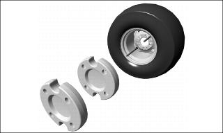
Installing Rear Wheel Weights
Installing Weight Kits With Threaded Rods
1. Install one nut and lockwasher on each rod approximately two inches from end.
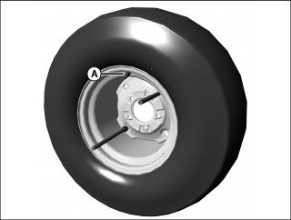
2. Note location of tire valve stem (A). Install rods through square holes in rim center as shown.
3. Install lockwasher and nut on rods on back side of rim center.
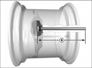
4. Position nuts to extend rods to length (B) shown in chart.
5. Install weight(s) as shown for each kit.
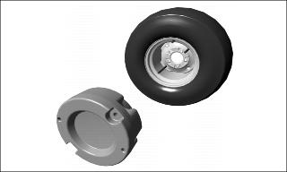
Installing Weight Kits With Bolts
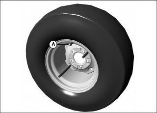
1. Note location of tire valve stem (A). Install bolts through square holes in rim center as shown.
2. Install weight(s) as shown for each kit.
BM17972 Weight Kit
Kit includes one 23kg (50 lb) weight. BM17977 hardware kit is required to install one weight. BM18101 hardware kit is required to install two weights.
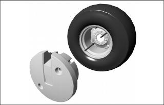
BM17973 Weight Kit
Kit includes one 33kg (72 lb) weight. BM18089 hardware kit is required to install one weight.
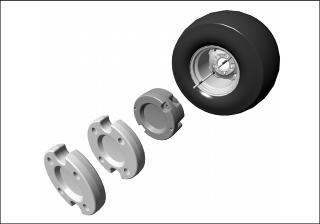
BM17972 and BM17973 Weight Kits Combined
BM17977 hardware kit is required to install one BM17973 weight and one BM17972 weight. BM18101 hardware kit is required to install one BM17973 weight and two BM17972 weights.
BM17976 Weight Kit
Kit includes one 23kg (50 lb) plastic coated weight and hardware.
Using Tire Chains
Tire chains are recommended for use with snowthrower and snowblower attachments; and, under certain conditions, blade attachments.
See your Attachment Operator's Manual for tire chain recommendations. See your John Deere dealer for tire chains.
Mowing Tips
The following recommendations will produce the best lawn cut quality and appearance:
· Keep mower blades sharp. Dull blades will tear grass; tips of grass will then turn brown.
· Cutting grass too short may kill grass and let weeds grow easily.
· Adjust cutting height to remove only 1/3 of the grass at a time.
· Mow grass often. Short grass clippings will decay quickly.
· Mow with engine at full throttle.
· Adjust travel speed to match mowing conditions:
· Travel at slow speed when you mow thick, tall grass, make sharp turns, trim around objects, or when mulching.
· Travel at moderate speed when you mow thin grass.
· Use a different mowing pattern each time you mow. Overlap mowing paths 50 to 100 mm (2 to 4 in.).
· Drive over ridges and through shallow ditches straight-on, not at an angle.
· A thick layer of mulched leaves can prevent sunlight from getting to grass and smother it. Taller grass heights allow mulched leaves to dispense easier in lawn. Mulch leaves several times if needed.
· Use a thatcher in late spring or summer to pull up dead grass and aerate ground.