
Assembly
Identify Parts
• Warranty Cards and Warranty Statement
Charge and Connect Battery
1. Remove and discard the red positive (+) protective cap from the positive (+) battery terminal.
• Battery is fully charged at 12.6 volts.
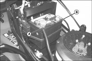
3. Connect positive (+) battery cable (A) to battery.
4. Connect negative (-) battery cable (B).
5. Apply general purpose grease or silicone spray to terminal to help prevent corrosion.
6. Slide red cover over positive battery cable.
Install Steering Wheel
1. Install steering wheel onto steering shaft. Turn steering wheel to position front wheels straight and facing forward.
3. Put John Deere Multi-Purpose lubricant or an equivalent on the steering shaft.
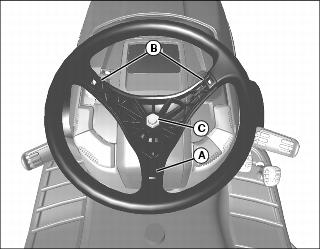
4. Install steering wheel onto steering shaft with one spindle (A) positioned at 180? at bottom of wheel and spindles (B) at approximately 45? at top of wheel.
5. Install nut (C) and tighten to 38 N•m (28 lb-ft).
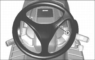
6. Install cover (D) so that the logo is on the right side facing up.
Install Seat Springs
IMPORTANT: Avoid damage! To prevent damage to seat switch and seat base, do not operate without suspension coils in place. |
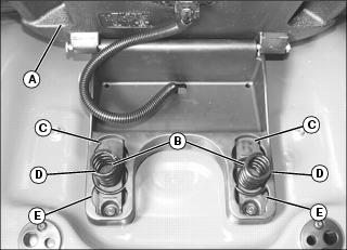
1. Raise seat (A) and install two springs (B) in one of three slotted areas in seat base.
• Move coils to front position (C) for softest ride.
• Move coils to middle position (D) for average ride.
• Move coils to rear position (E) for firm ride.
Remove Shipping Support Rod (54 Mower)
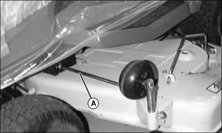
1. Remove support rod (A) from left side of deck.
Install Mower Gage Wheels
NOTE: Gage wheels are installed upside down in mower deck for shipping.
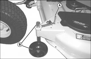
• Pull pin (A) outward and remove wheel and shaft (B) installed upside down on mower deck. Install from the bottom of deck to proper hole position, as shown. Release pin to lock wheel in position.
2. Adjust mower level before operation.
Check Tire Pressure
Check tire pressure. (See Checking Tire Pressure in the SERVICE MISCELLANEOUS section.)
Adjust Mower Deck Level
Adjust mower deck level. (See Adjusting Mower Level in the OPERATING section.)
Check Engine Oil Level
Check engine oil level. (See Checking Engine Oil Level in the SERVICE ENGINE section.)
Check Machine Safety System
Perform safety system check to make sure the electronic safety interlock circuit is functioning properly. Perform all tests. (See Testing Safety System in the OPERATING section.)