
Service Transmission
Checking Transmission (Z225 and Z245)
The Z225 and Z245 transmission is a sealed component. No maintenance is required on this transmission. If you suspect any transmission problems, please contact your authorized dealer.
Transmission Oil (Z425, Z445 and Z465)
NOTE: Machine is filled with John Deere Low Viscosity HY-GARD® (J20D) transmission oil at the factory. Do not mix oils.
Use only Low Viscosity HY-GARD® (J20D) transmission oil. DO NOT use type “F” automatic transmission fluid.
IMPORTANT: Avoid damage! Use John Deere Low Viscosity HY-GARD® (J20D) transmission oil to reduce transmission noise and to increase response time for the hydraulics and power steering. |
John Deere Low Viscosity HY-GARD® (J20D) transmission oil is specially formulated to provide maximum protection against mechanical wear, corrosion, and foaming. It may be used in all operating temperatures.
Checking Transaxle Oil Level (Z425, Z445 and Z465)
NOTE: On Z225 and Z245 models, the transaxle is a sealed component. No maintenance is required on this transaxle. If you suspect any transmission problems, please contact your authorized dealer.
1. Park machine safely on a level surface. (See Parking Safely in the SAFETY section.)
IMPORTANT: Avoid damage! Hot hydraulic oil will expand and show incorrect oil level. Check oil level: |
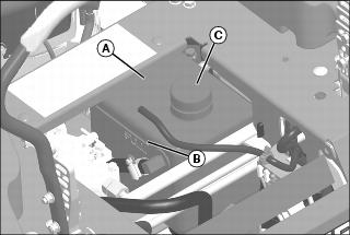
4. Locate transaxle oil reservoir (A) at rear of machine. Reservoir is marked FULL (B).
IMPORTANT: Avoid damage! Contamination can damage the hydraulic system. Clean thoroughly around reservoir fill cap before opening. |
5. If oil level is low, clean area around reservoir cap (C).
7. Add John Deere Low Viscosity HY-GARD™ (J20D) until oil level is at FULL mark on reservoir.
10. Operate machine forward and in reverse several times.
11. Park machine safely on a level surface. (See Parking Safely in the SAFETY section.)
12. Wait at least 3 minutes for hydraulic oil to cool.
13. Check oil level again. Add oil if necessary.
Changing Transaxle Oil and Filter (Z425, Z445 and Z465)
NOTE: Z225 and Z245 models: The transaxle is a sealed component. No maintenance is required on this transaxle. If you suspect any transmission problems, please contact your authorized dealer.
Z425, Z445 and Z465 models: Changing transaxle oil and filter is not required as a regular service interval and should not be changed unless servicing other components.
1. Park machine safely on a level surface. (See Parking Safely in the SAFETY section.)
IMPORTANT: Avoid damage! Contamination can damage the hydraulic system. Clean thoroughly around reservoir fill cap before opening. |
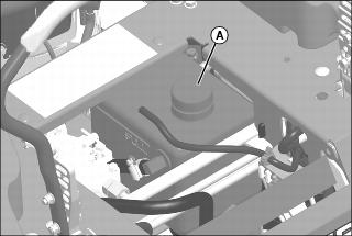
2. Raise operator’s seat, and clean area around reservoir cap (A). Remove cap.
Picture Note: View from rear of machine.
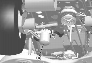
3. Clean area around hydraulic oil filter (B).
4. Place drain pan with at least a 6.1 L (1.65 gal) capacity under hydraulic oil filter, turn filter counterclockwise to remove and allow oil to drain completely.
5. Apply a film of clean oil on gasket of new filter.
6. Install filter. Turn filter clockwise until gasket makes contact with the mounting surface. Tighten 1/2 to 3/4 turn after gasket contact.
NOTE: Reservoir capacity is approximately 5.2 L (1.4 gal). Total system capacity with filter is approximately 6.1 L (1.65 gal).
7. Fill oil reservoir with approximately 5.2 L (1.4 gal) of oil.
10. Move throttle lever to the 3/4 fast idle position.
12. Run engine in full forward position for five minutes and then cycle motion control levers forward and rearward several times. Check for leaks around filter.
13. Stop the engine. Check oil level in reservoir. Add oil as necessary.
Checking and Adjusting Neutral Creep
Check neutral creep with engine running, motion control levers in the start/shutdown position, park brake off, and machine on level ground.
If the machine creeps forward or reverse while motion control levers are in the start/shutdown position, adjust the motion control lever linkages:
1. Park machine safely. (See Parking Safely in the SAFETY section.)
Z225 and Z245
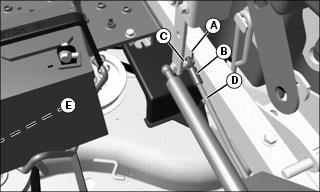
Picture Note: Right side components shown.
• Remove spring locking clip (A) on rod end (B), then remove rod end from pivot pin (C). Turn rod end on rod (D) in (clockwise) to decrease forward creep and out (counterclockwise) to decrease reverse creep. Repeat procedure, as necessary, on opposite side (E). Install rod ends back onto arms and secure with spring locking clips.
Z425, Z445 and Z465
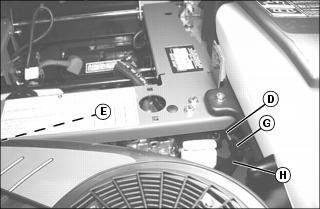
Picture Note: Z425 shown. Z445 and Z465 similar.
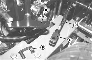
Picture Note: Closeup of Z445 shown.
• Remove locking pin (F) on yoke end (G), then remove yoke end from arm (H). Turn black yoke end on rod (D) in (clockwise) to decrease forward creep and out (counterclockwise) to decrease reverse creep. Repeat procedure, as necessary, on opposite side (E). Install yoke ends back onto arms and secure with locking pin.
Adjusting Tracking
If the machine does not track in a straight line while going in full forward position, adjust the tracking:
NOTE: Use the 13 mm wrench (A) on one end of the deck height pin for adjusting the tracking bolts.
1. Park machine safely. (See Parking Safely in the SAFETY section.)
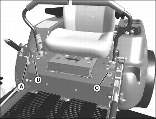
NOTE: Tracking bolts limit top forward speed. If both levers hit against the tracking bolts, turn both bolts counterclockwise equal amounts until only one bolt contacts the lever. This will achieve maximum forward speed.
• If machine tracks to the left, turn tracking bolt (B) clockwise.
• If machine tracks to the right, turn tracking bolt (C) clockwise.
Cleaning Transaxle Cooling Fans (Z225)
• Clear work area of bystanders. • Wear eye protection when using compressed air for cleaning purposes. |
1. Park machine safely. (See Parking Safely in the SAFETY section.)
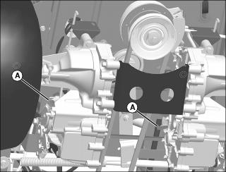
Picture Note: View from rear of machine.
2. Clean transaxle fan fins (A) and around exterior of each fan with a rag, brush, or compressed air.
Checking and Replacing Transaxle Drive Belt (Z225 and Z245)
NOTE: The transmission drive belt is self-adjusted using a spring tensioner and does not require a tension adjustment.
Checking Belt:
1. Park machine safely. (See Parking Safely in the SAFETY section.)
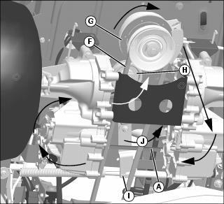
Picture Note: View from rear of machine.
2. Inspect drive belt (A) for excessive wear, damage or stretching while in position on the engine sheave, transmission sheaves, and drive belt tensioner sheave.
Replacing Belt:
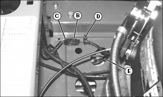
1. Disconnect electric clutch wiring connector (B) from main wiring harness connector (C).
2. Remove clutch wiring harness from retaining clip (D), and lower harness and connector (C) through hole (E).
3. Remove mower deck drive belt (F). (See Replacing Mower Deck Drive Belt in the SERVICE MOWER section.)
4. Remove drive belt (A) from engine sheave (G), transmission sheaves and idler sheave (H).
• To make removal and installation of the belt easier, carefully rotate the spring loaded idler (I) counterclockwise (J), and remove belt.
5. Install belt onto engine sheave, transmission sheaves and idler sheave as shown by arrows.
6. Install mower deck drive belt.
7. Install electric clutch wiring harness back through frame hole and connect to main wiring harness. Secure harness onto frame with retaining clip.
Checking and Replacing Pump Drive Belt (Z425, Z445 and Z465)
NOTE: The transmission drive belt is self-adjusted using a spring tensioner and does not require a tension adjustment.
Checking Belt:
1. Park machine safely. (See Parking Safely in the SAFETY section.)
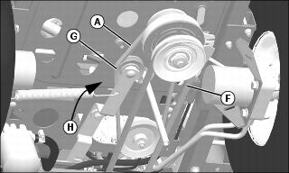
Picture Note: View from rear of machine.
2. Inspect belt (A) for excessive wear, damage or stretching while in position on the transmission sheave and drive belt tensioner sheave.
Replacing Belt:
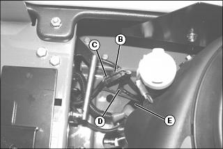
1. Disconnect electric clutch wiring connector (B) from main wiring harness connector (C).
2. Remove clutch wiring harness from retaining clip (D), and lower harness end through hole (E).
3. Remove mower deck drive belt (F). (See Replacing Mower Deck Drive Belt in the SERVICE MOWER section.)
4. Remove drive belt (A) from drive sheaves and idler sheave.
• To make removal and installation of the belt easier, carefully rotate the spring loaded idler (G) clockwise (H), and remove belt.
5. Install drive belt onto drive sheaves and idler sheave as shown.
6. Install mower deck drive belt.
7. Install electric clutch wiring harness back through frame hole and connect to main wiring harness. Secure harness onto frame with retaining clip.