
Service the Battery Safely

Removing and Installing the Battery
Removing
1. Park machine safely. (See Parking Safely in the SAFETY section.)
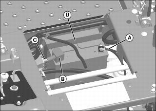
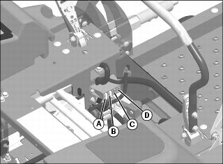
3. Disconnect negative (-) battery cable (A).
4. Push red cover (B) away from positive (+) battery terminal and remove cable (C) from battery.
5. Remove hold down strap (D).
6. Lower seat slightly to gain clearance for battery removal. Seat can be removed to have better access to the battery and make it easier to remove.
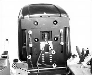
• To remove seat: Remove wiring harness connector (E) and harness plug (F) from seat. Remove retaining clip (G) and remove rod (H) holding seat to machine. Remove seat.
Installing
1. Place battery into battery tray so battery posts are facing toward rear of machine.
3. Connect positive (+) cable to battery first, then negative (-) cable.
4. Apply general purpose grease or silicone spray to terminal to help prevent corrosion.
5. Slide red cover over positive battery terminal.
7. Install wiring harness connector and harness plug on seat, if removed.
Cleaning Battery and Terminals
1. Park machine safely. (See Parking Safely in the SAFETY section.)
2. Disconnect and remove battery.
3. Wash battery with solution of four tablespoons of baking soda to one gallon of water. Be careful not to get the soda solution into the cells.
4. Rinse the battery with plain water and dry.
5. Clean terminals and battery cable ends with wire brush until bright.
7. Attach cables to battery terminals, beginning with the positive cable, using washers and nuts.
8. Apply spray lubricant to terminal to prevent corrosion.
Using Booster Battery
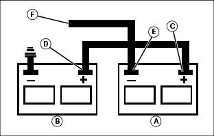
1. Connect positive (+) booster cable to booster battery (A) positive (+) post (C).
2. Connect the other end of positive (+) booster cable to the disabled vehicle battery (B) positive (+) post (D).
3. Connect negative (–) booster cable to booster battery negative (–) post (E).
4. Connect the other end (F) of negative (–) booster cable to a metal part of the disabled machine engine block away from battery.
5. Start the engine of the disabled machine and run machine for several minutes.
6. Carefully disconnect the booster cables in the exact reverse order: negative cable first and then the positive cable.
Replacing Headlight Bulb (If Equipped)
1. Park machine safely. (See Parking Safely in the SAFETY section.)
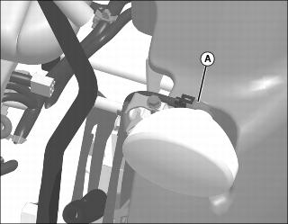
2. Turn bulb socket (A) 1/4 turn counterclockwise to remove.
3. Replace defective bulb with a new bulb.
4. Insert bulb socket into housing, push in and turn 1/4 turn clockwise to install.
Replacing Fuse
1. Park machine safely. (See Parking Safely in the SAFETY section.)
3. Pull blown fuse out of socket.
4. Check metal strip in fuse window and discard fuse(s) if strip is broken.