
Operating
Daily Operating Checklist
o Remove grass and debris from engine compartment and muffler area, and on top of mower deck, before and after operating machine.
o Check transaxle oil level - sight bottle (Z425, Z445, Z465).
o Check area below machine for leaks.
Avoid Damage to Plastic and Painted Surfaces
• Do not wipe plastic parts unless rinsed first. Using a dry cloth may cause scratches.
• Insect repellent spray may damage plastic and painted surfaces. Do not spray insect repellent near machine.
• Be careful not to spill fuel on machine. Fuel may damage surface. Wipe up spilled fuel immediately.
• Prolonged exposure to sunlight will damage hood surfaces.
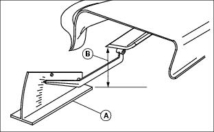
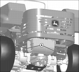
Mounting and Dismounting Machine
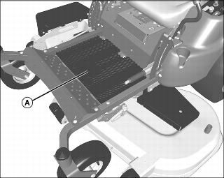
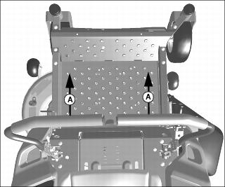
• Do not step on the mower deck when mounting and dismounting the machine.
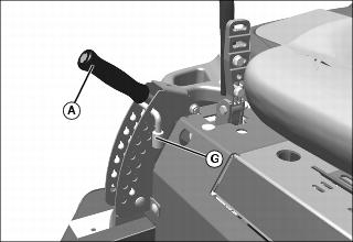
• Mount the machine from the front using the foot plate (A).
• Park machine safely before dismounting (see Parking Safely in the SAFETY section).
Adjusting Seat
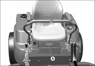
2. Slide seat forward or rearward to desired position.
Adjusting Armrests (If Equipped)
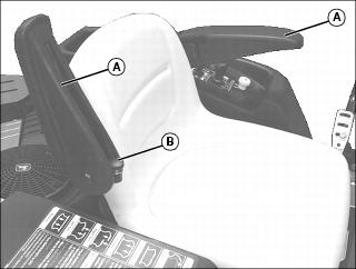
2. Turn adjustment knob (B) clockwise to lower armrest and counterclockwise to raise armrest. Lower armrests.
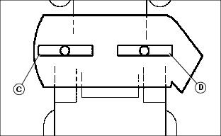
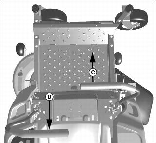
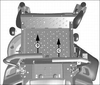
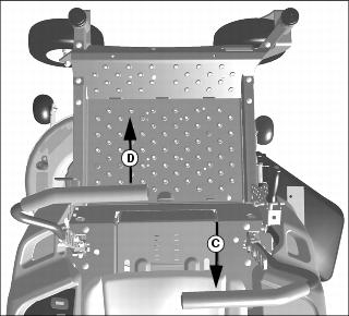
Adjusting Motion Control Levers
1. Park machine safely. (See Parking Safely in the SAFETY section.)
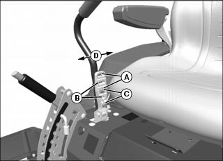
2. To adjust motion control lever height, remove two bolts and nuts and raise or lower each control lever to your comfort level.
• For highest lever position, use holes (A).
• For medium lever position, use holes (B).
• For lowest lever position, use holes (C).
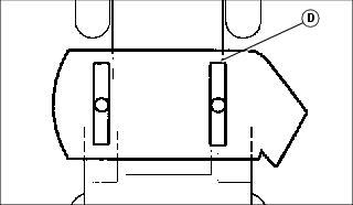
3. You can also adjust motion control levers slightly forward or rearward (D) within slotted holes.
Adjusting Mower Level
NOTE: Mower wheels should not contact the ground when leveling the deck.
1. Park machine safely. (See Parking Safely in the SAFETY section.)
2. Inflate tires to the correct pressure.
3. Position caster wheels to the forward driving position.
4. Set mower to preferred cutting height, and lower deck into the mowing position.
5. Measure mower level (side-to-side).
Picture Note: A convenient leveling gauge (A) (AM130907) is available from your dealer.
a. Position mower blades as follows and measure from each outside blade tip (B) to the level surface.
b. Turn left blade (C) as shown. Hold drive belt and turn right blade (D) as shown. Take measurement for both blades.
The difference between blade measurements must not be more than 3 mm (1/8 in.).
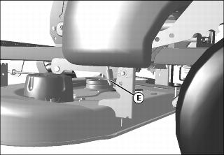
c. Adjust mower level, if necessary, by turning rear nuts (E) clockwise to raise the side of the mower deck, or counterclockwise to lower the mower deck.
6. Measure mower level (front-to-rear).
a. Turn right blade (D) so blade tip points straight forward.
b. Measure from blade tip to the surface. Take measurement for both blades. The front blade tip must be 3 - 6 mm (1/8 - 1/4 in.) lower than rear blade tip.
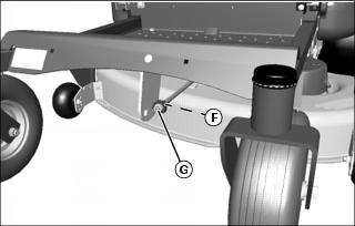
c. 42 inch mower deck: Adjust mower level, if necessary, by loosening rear nut (F) on front lift rod. Turn front nut (G) clockwise to raise front of mower or counterclockwise to lower it. Tighten rear nut after adjustment is complete.
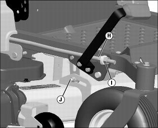
d. Z445 (54 in. HC) and Z465 (62 in.) mower decks: Adjust mower level, if necessary, by loosening nut (H). Turn front nut (I) clockwise to lower front of mower or counterclockwise to raise front of mower. Tighten rear nut after adjustment is complete. Make certain, at the start, that bolt (J) is at top of slot as shown. If either side is not carrying load at the completion of leveling, the bolt can be loosened and slid downward in the slot slightly to even the load between the hangers on either side.
Picture Note: 48 in. deck shown.
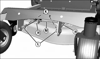
e. 48 and 54 (all other models): Adjust mower level, if necessary, by loosening rear nuts (K) on front lift rod. Turn front nuts (L) clockwise to raise front of mower or counterclockwise to lower it. Make sure front lift rod (M) contacts mower deck bracket on both sides (N) to maximize stability of deck. Tighten rear nut after adjustment is complete.
NOTE: Verify that deck will latch in transport position. If it does not latch, turn both rear adjusting nuts counter-clockwise equally to lower rear of deck until deck latch will engage. Check front lift rod adjustment, adjust if necessary.
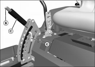
Adjusting Cutting Height
Cutting height can be adjusted from approximately 25-100 mm (1-4 in.). When mower deck is in transport position cutting height is approximately 100 mm (4 in.).
1. Check tire pressure and adjust as needed.
Picture Note: Z425, Z445, and Z465
• Z225 and Z245 - Pull upward on mower deck lift lever (A) and pull lever towards center of machine to lock in raised position.
• Z425, Z445, and Z465 - Push in button (B) and pull upward on mower deck lift lever (C) until in fully raised position.
• Z445 (54 in. HC Deck) - Push in button (B), push down on lift pedal, and pull upward on mower deck lift lever (C) until in fully raised position.
3. Insert the pin (G) in the proper hole for the desired height of cut.
• Z225 and Z245 - Lift slightly on mower deck lift lever, push slightly outward, and lower lift lever (A) onto pin (G).
• Z425, Z445, and Z465 - Push in button (B) and lower mower deck lift lever (C) onto pin (G).
• Z445 (54 in. HC Deck) - Place foot on lift pedal, push in button (B), and release lift pedal rearward while lowering mower deck lift lever (C) onto pin (G).
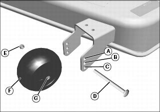
Adjusting Mower Wheels
1. Park machine safely on a level surface. (See Parking Safely in the SAFETY section).
2. Inflate tires to correct pressure.
3. Raise mower deck lift lever, and lock in transport position.
4. Adjust mower wheels to correct height:
42 Inch Mower
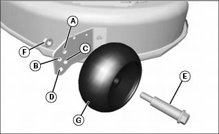
• Remove shoulder bolt (E) and nut (F). Move wheel (G) to proper hole position. Secure with shoulder bolt and nut. Tighten nut to 34 N•m (25 lb-ft).
48 Inch Mower (Z245)
• Remove shoulder bolt (E) and nut (F). Move wheel (G) to proper hole position. Secure with shoulder bolt and nut. Tighten nut to 34 N•m (25 lb-ft).
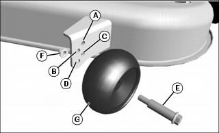
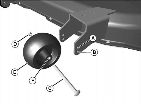
48 and 54 Inch Mowers (Z400 Series)
• Remove shoulder bolt (D) and nut (E). Move wheel (F) to proper hole position. Secure with shoulder bolt and nut. Tighten nut to 34 N•m (25 lb-ft).
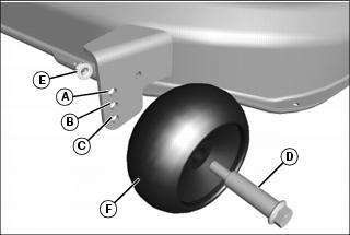
54 Inch High Capacity Mower (Z445)
• Remove carriage bolt (D) and nut (E). Move wheel (F) and axle (G) to proper hole position. Secure with carriage bolt and nut. Tighten nut to 24 N•m (18 lb-ft).
62 Inch Mower
• Remove carriage bolt (C) and nut (D). Move wheel (E) and axle (F) to proper hole position. Secure with carriage bolt and nut. Tighten nut to 24 N•m (18 lb-ft).
Testing Safety Systems

The safety systems installed on your machine should be checked before each machine use. Be sure you have read the machine operator manual and are completely familiar with the operation of the machine before performing these safety system checks.
Use the following checkout procedures to check for normal operation of machine.
If there is a malfunction during one of these procedures, do not operate machine. See your authorized dealer for service.
Perform these tests in a clear open area. Keep bystanders away.
Testing Park Brake Switch
1. Park machine safely. (See Parking Safely in the SAFETY section.)
Testing Park Brake
1. Park machine safely. (See Parking Safely in the SAFETY section.)
4. Try to push machine manually.
Testing Mower Engagement (PTO) Switch
1. Park machine safely. (See Parking Safely in the SAFETY section.)
Testing Seat Switch
1. Park machine safely. (See Parking Safely in the SAFETY Section.)
c. Move throttle lever up to maximum engine speed.
e. Raise up off seat. Do not get off machine.
d. Raise up off seat. Do not get off machine.
d. Raise up off seat. Do not get off machine.
Testing Motion Control Lever Switch
1. Park machine safely. (See Parking Safely in the SAFETY Section.)
a. With the park brake locked, start engine.
b. Move right motion control lever inward.
c. Move right motion control lever inward.
5. Repeat first and second test using left motion control lever.
Using Park Brake
Always lock the park brake and remove the key before leaving the machine unattended. |
Z200 Series
Setting Park Brake
1. Raise park brake lever to lock park brake.
Releasing Park Brake
1. Lower park brake lever to unlock park brake.
Z400 Series
Setting Park Brake
1. Press button, and raise park brake lever to lock park brake.
Releasing Park Brake
1. Press button, and lower park brake lever to unlock park brake.
Using Key Switch
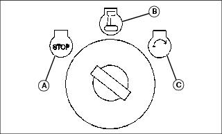
A - STOP (off) position - With key in the STOP position, all switched power is off, and engine should not run.
B - Run (on) position - Turn key from STOP to this position, and all switched power circuits will be on.
C - Start position - Turn key to start position to crank the engine. Release key after engine has started and it will automatically return to the on position. The engine will continue to run.
Using Mower Engagement Switch
• To Engage Mower - Pull mower engagement knob up.
• To Disengage Mower - Push mower engagement knob down.
Using the Hour Meter
• The hour meter shows the number of hours the engine has run. The hour meter does not accumulate hours with the engine off when the key is in the run position. Use the hour meter to determine when your machine has reached the recommended service intervals.
• Turn the key to STOP position when not using the machine.
Using the Motion Control Levers
Before using the machine, become familiar with the motion control levers and how they respond. It is essential to know how the machine accelerates, steers and stops.
The functions of the motion control levers are:
• Dual function neutral position.
Start/shutdown Position
• Motion control levers must be in the start/shutdown position (A) and the park brake locked (B) to start the engine.
• Forward and reverse movement of the motion control levers is prevented when levers are moved to the start/shutdown position.
• Operator can exit mower with the engine running when the mower engagement switch is disengaged, the motion control levers are in the start/shutdown position and the park brake is locked.
• Motion control levers must be in the start/shutdown position to safely enter and exit the operator seat.
Neutral Position
• Machine speed, motion, and direction can be controlled when the engine is running, motion control levers are in the neutral position (C), and the park brake is unlocked (D).
• To stop the machine for an emergency, move the motion control levers quickly back to the neutral position.
Forward and Reverse Travel
Straight forward and reverse travel takes practice. If the machine does not track in a straight line when going forward or reverse, the motion control lever tracking may need adjusting.
1. Move throttle lever to the mow position.
3. Move both motion control levers from the start/shutdown position inward to the neutral position.
4. Move the motion control levers forward to begin forward travel.
5. Move the motion control levers rearward to begin reverse travel.
6. To stop travel, move motion control levers back to the neutral position.
Forward Travel
1. Gradually move both motion control levers evenly forward (A) from neutral. To speed up, move the levers farther forward. To slow down smoothly, slowly move the levers toward neutral.
Reverse Travel
1. Look down and behind, then gradually move both motion control levers evenly rearward (B) from neutral. To speed up, move the levers farther rearward. To slow down smoothly, slowly move the levers toward neutral.
Left Turn
1. To turn slightly to the left, push right control lever (C) further forward than the left control lever (D).
2. To turn sharply to the left, push right control lever (C) forward and pull left control lever (D) rearward at the same time.
Right Turn
1. To turn slightly to the right, push left control lever (D) further forward than the right control lever (C).
2. To turn sharply to the right, push left control lever (D) forward and pull right control lever (C) rearward at the same time.
Starting the Engine
3. Push the mower engagement knob down to disengage the mower.
4. Set both motion control levers to the start/shutdown position.
5. Move throttle lever to set engine speed:
IMPORTANT: Avoid damage! Starter may be damaged if starter is operated for more than 20 seconds at a time: • Wait two minutes before trying again if engine does not start. |
6. Turn key switch to the start position.
7. After engine starts, release key switch to the run position and move throttle to mow position.
IMPORTANT: Avoid damage! Unnecessary engine idling may cause engine damage. Excessive idling can cause engine overheating, carbon build-up, and poor performance. |
8. Allow the engine to warm up for 20 seconds.
10. Set both motion control levers to the neutral position.
Engaging Mower
1. Adjust mower to desired cutting height.
4. Move both motion control levers to the neutral position.
5. Set throttle lever to the RUN position.
NOTE: For smoother engagement, deck can be engaged at transport position and then lowered to desired cut height.
6. Pull mower engagement switch up to engage mower.
NOTE: The travel speed and turn rate will vary with the amount that the control levers are moved.
7. Push motion control levers forward slowly. Mow at a safe travel speed.
Stopping the Engine
1. Stop machine on a level surface, not on a slope.
2. Push the mower engagement switch down to disengage mower.
3. Move the motion control levers to the start/shutdown position.
5. Move throttle lever to the shutdown position.
6. Allow the engine to cool down for 20 seconds.
7. Turn ignition key to STOP (off) position.
Always lock the park brake and remove the key before leaving the machine unattended. |
Moving Machine by Hand
IMPORTANT: Avoid damage! Transmission damage may occur if the machine is towed or moved incorrectly: |
Z225 and Z245 Models:
1. Pull out both bypass valve levers (A) at rear of machine.
3. Push machine to desired location.
4. Push in both bypass valve levers.
Z425, Z445 and Z465 Models:
When the machine needs to be moved without starting the engine, use the bypass valves:
NOTE: The bypass valves must be fully turned clockwise (closed) during normal vehicle operation.
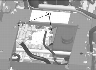
3. Turn bypass valves (A) on both sides of pump 1/4 - 1/2 turn counterclockwise (open position).
5. Push machine to desired location. Due to hydraulic system drag, machine will move slowly.
IMPORTANT: Avoid damage! The bypass valves can be damaged if overtightened. Use care not to overtighten. |
NOTE: Bypass valves should be hand tightened only.
6. Turn both bypass valves clockwise (closed position) until tight.
Unplugging Mower, Bagger, or Material Collection System
Checking For Plugging While Driving
If grass builds up in front of mower discharge chute, check for plugged chute or problems with blower assembly (if equipped).
If there is a trail of clippings behind mower or clippings blow to the side, check for plugged chute, full collector bags, or problems with blower assembly.
Removing Debris From Inspection Points:
1. Park machine safely. Wait for all moving parts to stop before getting off to inspect machine.
2. Open hopper cover. Check chute outlet.
3. Remove chute from mower deck or blower assembly. Check chute inlet.
4. Check under mower deck for debris.
Using Wash Port to Clean Mower Deck
NOTE: Follow this procedure after each use to prevent buildup and remove corrosive lawn chemicals.
1. Park machine safely. (See Parking Safely in the Safety section).
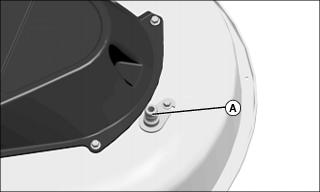
2. Attach a garden hose with quick-coupler to wash port (A) on the mower deck.
7. Flush water under deck for approximately one minute.
10. Turn off water and remove garden hose from wash port.
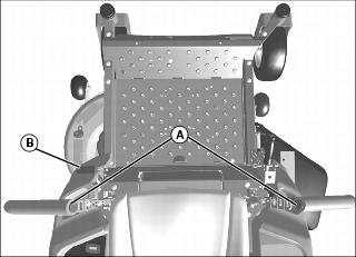
Transporting Machine on Trailer
NOTE: Trailer capacity must exceed combined machine weight and attachment weight. (See Specifications section in operator’s manual).
Be sure trailer has all the necessary lights and signs required by law.
1. Park trailer on level surface.
2. Raise mower deck before driving machine onto trailer.
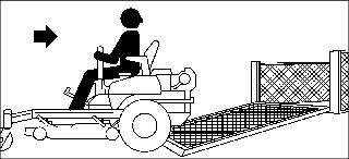
3. Back machine onto heavy-duty trailer with full-width ramp.
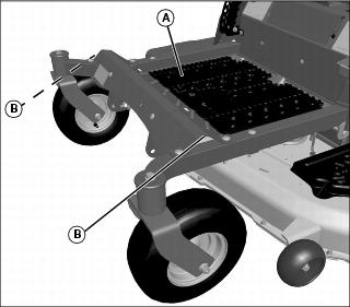
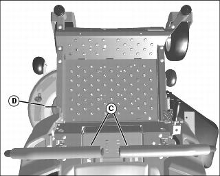
4. Remove rubber mat (A) from foot deck.
5. Lower mower deck completely.
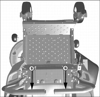
7. Fasten front of machine at both sides of the frame at points (B) to trailer with heavy-duty straps, chains, or cables. Straps must be directed down and outward from machine.
8. Turn off machine and remove key.
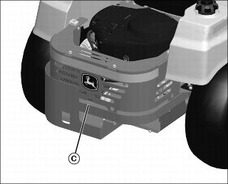
Picture Note: Shielding shown is not on all models.
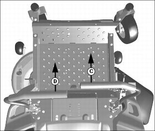
9. Fasten rear of machine at center of frame at point (C) to trailer with a heavy-duty strap, chain, or cable. Strap must be directed down and outward from machine.
Mowing Tips
• Mow grass with throttle lever in the full fast / mow position.
• Keep mower deck and discharge chute clean.
• Properly level mower deck for a smooth cut.
• Use a travel speed that fits the conditions:
• Mow tall or wet grass twice. Cut grass at half desired height – then cut at desired height.
• Travel slow when mowing tall or thick grass.
• Avoid damaging grass by slipping or skidding machine drive wheels. Practice smooth control lever movements.
• When performing sharp turns, do not allow inside machine drive wheel to stop and twist on grass.