
Operating
Daily Operating Checklist
o Check fuel level. See SERVICE MISCELLANEOUS section, Using Proper Fuel and Stabilizer
o Check coolant level (Liquid cooled models).
o Remove grass and debris from engine compartment and muffler area, and on top of mower deck before and after operating machine.
o Check transaxle oil level - sight bottle.
o Check area below machine for leaks.
IMPORTANT: Avoid damage! Using stale, contaminated or improper fuel can result in engine and fuel system damage. Repairs caused by stale, contaminated or improper fuel are not covered by warranty. |
Avoid Damage to Plastic and Painted Surfaces
• Do not wipe plastic parts unless rinsed first. Using a dry cloth may cause scratches.
• Insect repellent spray may damage plastic and painted surfaces. Do not spray insect repellent near machine.
• Be careful not to spill fuel on machine. Fuel may damage surface. Wipe up spilled fuel immediately.
• Prolonged exposure to sunlight will damage hood surfaces.
Adjusting Seat
Adjusting Seat Position
1. Push lever (A) to the left.
2. Slide seat forward or rearward to desired position.
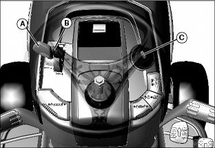
Adjusting Ride Comfort
IMPORTANT: Avoid damage! To prevent damage to seat switch and seat base, do not operate without suspension coils in place. |
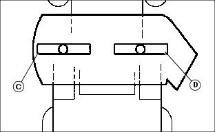
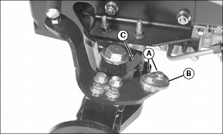
2. Rotate suspension coils into desired position:
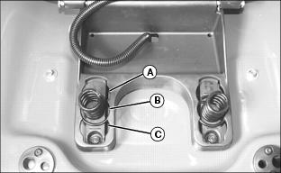
• Move coils to front position (A) for softest ride.
• Move coils to middle position (B) for average ride.
• Move coils to rear position (C) for firm ride.
NOTE: Additional suspension coils can be installed for extra support. See your John Deere dealer.
Adjusting Cutting Height
Cutting height can be adjusted from approximately 25-100 mm (1-4 in.). When mower deck is in transport position cutting height is approximately 100 mm (4 in.).
Mower cutting height increments are identified on decal around the cutting height knob. To change or attain cutting height desired:
1. Check tire pressure and adjust as needed.
Picture Note: X500 model shown.
• For X500 models: Push lift pedal (A) to raise mower deck to highest (transport) position. Pull up on mower lift lock lever (B) to lock in raised position.
• For X530, X534 and X540 models: Pull up on hydraulic mower lift lever (B) to raise mower deck.
3. Turn mower cutting height knob (C) to desired cutting height position. Mower will be at this cutting height each time it is lowered.
Checking and Adjusting Mower Level
NOTE: Mower wheels should not contact the ground when leveling the deck.
Method One
1. Park machine safely on a level surface. (See Parking Safely in the SAFETY section).
2. Inflate tires to the correct pressure.
3. Adjust operator seat to the rear most position.
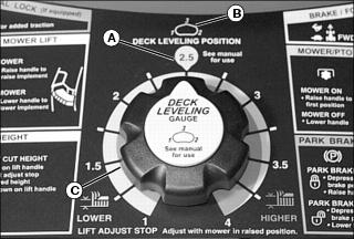
4. The label for the cutting height knob is located on the console of the machine. This label shows deck leveling position (A) and location of deck leveling adjustment points (B). The location of adjustment points will vary slightly between decks:
• Adjustment point 1 is located on the left rear deck rim.
• Adjustment point 2 is located on the right rear deck rim.
• Adjustment point 3 is located on the front deck hanger bracket.
5. Set mower cutting height knob (C) to deck leveling position 2.5 (A), and lower deck against stop.
6. Adjust mower deck gage wheels as necessary so they do not contact the ground surface.
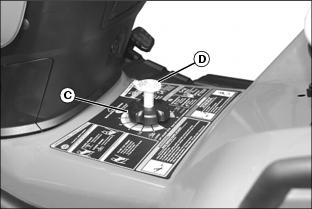
7. Remove the mower deck level gage (D) stored in the mower cutting height knob (C).
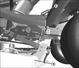
8. Adjust mower deck side-to-side level:
NOTE: Adjustment points 1 and 2 have a raised marker (E) for side-to-side measurement.
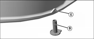
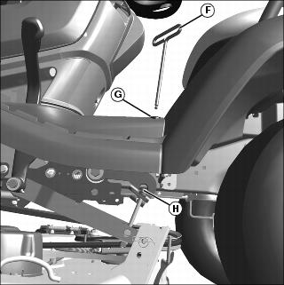
a. Insert provided deck level wrench (F) into top port opening (G) on fenderdeck until end of wrench mates with adjustment bolt (H).
b. Rotate wrench (F) until gauge (D) just slips under deck at adjustment point 1.
c. Repeat procedure on opposite side of deck for adjustment point 2.
NOTE: If an adjustment of more than 1/8 in. is required, adjust both points alternately. A large adjustment on one side can move the other side in the opposite direction.
d. Repeat step a, b, and c, as necessary.
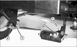
9. Adjust mower deck front-to-back level:
NOTE: Adjustment point 3 has a stamped “3” on side of front deck hanger bracket (I).
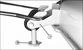
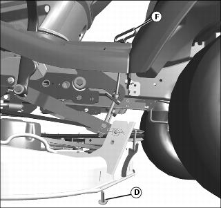
a. Use gage (D) to measure the height between the floor and front deck hanger bracket at adjustment point 3.
b. Adjust mower level, if necessary, by loosening rear nut (J) equally on each side of front lift rod. Turn front nut (K) equally on each side clockwise to raise front of mower or counterclockwise to lower it until gage just slips under adjustment point 3. Tighten rear nuts after adjustment is complete.
NOTE: Before storing gage, verify that deck will latch in transport position. If it does not latch, turn both rear adjusting nuts counter-clockwise equally to lower rear of deck until deck latch will engage. Check front draft arm adjustment, adjust if necessary.
10. Return the gage to its storage position. Store deck level gauge in safe area away from machine for future use.
Method Two
1. Park machine safely. (See Parking Safely in the SAFETY section.)
2. Inflate tires to the correct pressure.
3. Set mower cutting height knob to preferred cutting height, and lower deck into the mowing position.
4. Measure mower level (side-to-side).
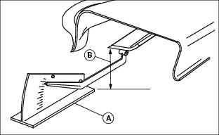
a. Position mower blades as follows and measure from each outside blade tip (B) to the level surface.
b. Turn left blade (C) as shown. Hold drive belt and turn right blade (D) as shown. Take measurement for both blades.
The difference between blade measurements must not be more than 3 mm (1/8 in.).

c. Insert provided deck level wrench (E) into top port opening (F) on fenderdeck until end of wrench mates with adjustment bolt (G).
d. Rotate wrench (E) clockwise to raise the side of the mower deck (H), or counterclockwise to lower the mower deck. Repeat on opposite side of mower deck.
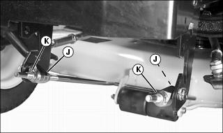
5. Measure mower level (front-to-rear).
a. Turn right blade (D) so blade tip points straight forward.
b. Measure from blade tip to the surface. Take measurement for both blades. The front blade tip must be 3 - 6 mm (1/8 - 1/4 in.) lower than rear blade tip.
c. Adjust mower level, if necessary, by loosening rear nut (I) equally on each side of front lift rod. Turn front nut (J) equally on each side clockwise to raise front of mower or counterclockwise to lower it. Tighten rear nuts after adjustment is complete. Store deck level wrench is safe area away from machine for future use.
NOTE: Verify that deck will latch in transport position. If it does not latch, turn both rear adjusting nuts counter-clockwise equally to lower rear of deck until deck latch will engage. Check front lift rod adjustment, adjust if necessary.
Adjusting Mower Wheels
1. Park machine safely on a level surface. (See Parking Safely in the SAFETY section).
2. Inflate tires to correct pressure.
• X500 - Push lift pedal to raise mower deck to transport position. Lock in raised position with mower lift lock lever.
• X530, X534, X540 - Pull up on mower lift handle to raise deck to transport position.
5. Lower mower to cutting position.
6. Measure distance between mower wheels and ground surface. All wheels should be 6-13 mm (1/4-1/2 in.) from ground.
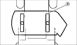
7. Adjust mower wheels to correct height:
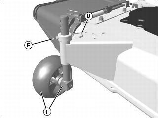
• 48 and 54 Mower - Remove locking clip (D), pull pin (E) outward, and move wheel and shaft (F) to proper hole position. Install pin and locking clip to lock wheel in position.
Testing Safety Systems

The safety systems installed on your machine should be checked before each machine use. Be sure you have read the machine operator manual and are completely familiar with the operation of the machine before performing these safety system checks.
Use the following checkout procedures to check for normal operation of machine.
If there is a malfunction during one of these procedures, do not operate machine. See your authorized dealer for service.
Perform these tests in a clear open area. Keep bystanders away.
Testing Park Brake Switch
1. Park machine safely. (See Parking Safely in the SAFETY section.)
Testing Park Brake
1. Park machine safely. (See Parking Safely in the SAFETY section.)
4. Try to push machine manually.
Testing Mower Engagement (PTO) Switch
1. Park machine safely. (See Parking Safely in the SAFETY section.)
Testing Seat Switch
Test 1
2. Move throttle lever to maximum speed position.
5. Raise up off seat. Do not get off machine.
Test 2
4. Raise up off seat. Do not get off machine.
Test 3
3. Raise up off seat. Do not get off machine.
Testing Reverse Implement Option (RIO)
Before backing up, carefully check the area around the machine. |
1. Park machine safely. (See Parking Safely in the SAFETY section.)
3. Engage PTO to start attachment.
4. Look behind the vehicle to be sure there are no bystanders.
5. Begin reverse travel by depressing reverse foot pedal.
Using Park Brake
Always lock the park brake and remove the key before leaving the machine unattended. |
Locking Park Brake
1. Push and hold down brake pedal.
2. Pull up park brake lever to lock park brake.
3. Release brake pedal. Pedal should stay down and park brake lever should stay up in locked position.
Unlocking Park Brake
1. Push and hold down brake pedal.
2. Push down park brake lever to unlock park brake.
3. Release brake pedal. Pedal should come up to operating position.
Using Key Switch and Headlights
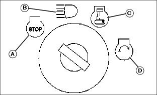
Engine Off
NOTE: Headlights will drain the battery rapidly if key switch is left in headlights on position (B) with the engine off.
• To turn headlights on, turn key switch to headlights on position (B).
• To turn headlights off, turn key switch to STOP position (A).
Engine On
• To turn headlights on, start engine, then turn key switch from run position (C) to headlights on position (B).
• To turn headlights off, turn key switch from headlights on position (B) to run position (C).
Using Instrument Panel
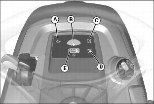
A - Oil Pressure Indicator
The Oil Pressure Indicator will come on when you turn the key to the run position. Indicator should go out when engine is started. If indicator comes on during operation, engine oil pressure is too low. Stop engine and perform appropriate service.
B - Fuel Gauge
The Fuel Gauge shows approximately how much fuel is in the fuel tank.
C - Coolant Temperature Indicator (X540)
The Coolant Temperature Indicator will come on during operation if the coolant temperature is above normal operating temperature. If mower is engaged, it will automatically stop. If coolant is above normal operating temperature, let engine cool at idle speed until indicator goes off. Stop engine and perform appropriate service.
D - Mower / PTO Indicator
The Mower / PTO Light will come on if mower/PTO engagement lever is pulled out when you turn the key to the run position. Mower / PTO light will come on if mower / PTO engagement lever is pulled outward.
E - Hour Meter
The Hour Meter shows the number of hours the engine has run.
NOTE: The hour meter is counting time if the decimal point is blinking.
Starting the Engine
NOTE: Engine will not start unless park brake is applied and mower is disengaged.
2. Make sure mower /PTO engagement switch is disengaged.
• If engine is cold, move throttle lever (A) between the half throttle and fast throttle positions.
• If engine is warm, move throttle lever (A) to slow throttle position.
• If engine is cold, push and hold choke lever (B) all the way up to the choke position.
• If engine is warm, push and hold choke lever (B) half way up or do not use at all depending on engine temperature.
IMPORTANT: Avoid damage! Starter may be damaged if starter is operated for more than 20 seconds at a time: • Wait two minutes before trying again if engine does not start. |
6. Turn key (C) to start position for no more than 5 seconds.
7. Release key to run position and release choke lever when engine starts. If engine does not start:
b. Hold choke lever in the choke position.
c. Turn key to start position again for no longer than 5 seconds. Release key and choke lever when engine starts.
d. Repeat procedure if necessary.
IMPORTANT: Avoid damage! Unnecessary engine idling may cause engine damage. Excessive idling can cause engine overheating, carbon build-up, and poor performance. |
8. Run engine at half throttle for 30-60 seconds to allow warm-up before operating.
Stopping the Engine
2. Move throttle lever to half throttle position and allow engine to run at half throttle for several seconds.
Using Travel Controls
Forward Travel
3. Push down slowly on forward pedal until desired travel speed is obtained.
4. Release forward pedal and machine will automatically return to neutral and stop.
Reverse Travel
NOTE: Any operating attachment will stop as the reverse foot pedal is depressed with attachment engaged. Reverse attachment operation is possible using the Reverse Implement Option (RIO).
2. Push mower engagement knob down to the off position to disengage attachment.
3. Look down and behind the machine to be sure there are no bystanders nearby.
4. Push down slowly on reverse pedal.
Stopping
1. Release either travel pedal, machine will automatically return to neutral and stop.
Using Cruise Control
Use cruise control when you want to maintain travel speed without having to hold the forward travel pedal down. Cruise control operates only for forward travel.
Engaging Cruise Control
1. Push forward pedal down until you reach desired travel speed.
3. Remove foot from forward pedal.
Disengaging Cruise Control
NOTE: Cruise control will also disengage if forward travel pedal is pressed.
Adjusting Tilt Steering Wheel (X534, X540)
Steering wheel has five tilt positions:
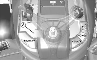
• Lift and hold lever (A) up and move wheel to a comfortable operating position.
• Release lever and move wheel slightly up or down until lever drops into the nearest position and locks wheel.
Using the Reverse Implement Option (RIO)
NOTE: Operating the mower while backing up is strongly discouraged. The Reverse Implement Option should be used only when operating another attachment or when the operator deems it necessary to reposition the machine with the mower engaged.
1. Stop forward travel. Allow attachment to run.
2. Look down and behind the machine to be sure there are no bystanders.
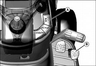
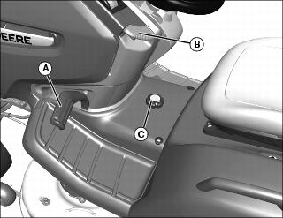
3. Lift mower engagement switch (A) past the mower engagement position then depress reverse foot pedal (B) slightly.
NOTE: If the attachment stops while positioning the machine, return mower engagement lever to off position. Repeat this procedure from the beginning.
4. As the machine begins to move backward, release the mower engagement lever and position the machine.
5. Resume forward travel. The attachment should continue operating.
6. Repeat procedure to position the machine again.
Using Mower Attachment / Mower Lift
NOTE: If the machine is equipped with a lift assist spring, make sure the tension is properly adjusted to support the weight of the mower deck or attachment installed.
Mowing Position
Mower floats along ground contour while maintaining desired cutting height. The mower will always float up and back down onto the depth stop.
1. To place mower in mowing position:
Models with Mechanical Lift
• Press lift pedal, making sure mower lift lock lever is in lower position; select cut height on knob and release pedal to lower deck.
Models with Hydraulic Lift
• Pull up on hydraulic mower lift lever to raise mower deck. Select cut height on knob. Press down on hydraulic mower lift handle to lower deck.
Transport Position
Holds mower above ground level while traveling to and from worksite.
1. To place mower in the transport position:
Models with Mechanical Lift
• Pull up on mower lift lock lever to lock deck in transport (raised) position.
• Remove foot from lift pedal and mower stays up.
Models with Hydraulic Lift
• Pull up on hydraulic mower lift lever to raise mower deck.
Using Mower Engagement Lever
NOTE: Mower engagement operation will stop if reverse pedal is depressed. Understand the Reverse Implement Option (RIO) system before operating the mower.
1. Start the engine. If necessary, allow engine to warm up before operating mower.
NOTE: Always operate at maximum throttle speed when mower is engaged.
2. Move throttle lever to fast position.
3. Move mower engagement lever to desired position:
• Engage mower - Lift up on mower engagement lever to “l” position.
• Disengage mower - Push down on mower engagement lever to “O” position.
• Maintain mower engagement in reverse - Lift and hold mower engagement lever in the highest position. Depress reverse foot pedal to start moving in reverse, release mower engagement lever.
Using Traction Assist
IMPORTANT: Avoid damage! Incorrectly engaging traction assist may damage the transaxle. Reduce speed before engaging or disengaging traction assist. |
The traction assist is used to provide better traction when rear wheels start to slip. Do not use traction assist unless you are experiencing rear wheel slippage. Engaging traction assist will cause both rear wheels to drive equally to improve traction.
Engaging Traction Assist
2. Push traction assist pedal down to the foot rest. Traction assist will remain engaged as long as pedal is depressed.
NOTE: Turning radius is increased when traction assist is engaged.
Disengaging Traction Assist
1. Release traction assist pedal.
Once the load on the transmission is equalized and reduced, the traction assist will disengage automatically.
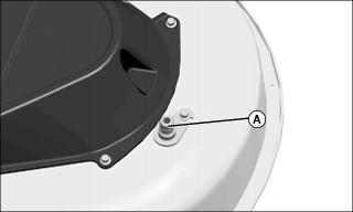
Using Wash Port to Clean Mower Deck
NOTE: Follow this procedure after each use to prevent buildup and remove corrosive lawn chemicals.
1. Park machine safely. (See Parking Safely in the Safety section).
2. Attach quick-coupler to garden hose.
3. Attach garden hose with quick-coupler to wash port (A) on the mower deck.
8. Flush water under deck for approximately one minute.
11. Turn off water and remove garden hose and quick-coupler from wash port.
12. Remove quick-coupler from garden hose and store for future use.
Moving Machine by Hand
IMPORTANT: Avoid damage! Transmission damage may occur if the machine is towed or moved incorrectly: |
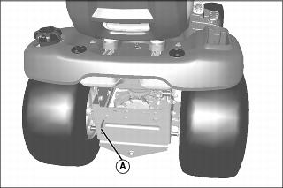
2. Pull out bypass valve lever (A) at rear of machine.
3. Push machine to desired location.
4. Push in bypass valve lever.
Unplugging Mower, Bagger, or Material Collection System
Checking For Plugging While Driving
If grass builds up in front of mower discharge chute, check for plugged chute or problems with blower assembly (if equipped).
If there is a trail of clippings behind mower or clippings blow to the side, check for plugged chute, full collector bags, or problems with blower assembly.
Removing Debris From Inspection Points:
1. Park machine safely. Wait for all moving parts to stop before getting off to inspect machine.
2. Open hopper cover. Check chute outlet.
3. Remove chute from mower deck or blower assembly. Check chute inlet.
4. Check under mower deck for debris.
Transporting Machine on Trailer
NOTE: Trailer capacity must exceed combined machine weight and attachment weight. (See Specifications section in operator’s manual).
Be sure trailer has all the necessary lights and signs required by law.
1. Park trailer on level surface.
2. Raise mower deck, if installed, before driving machine onto trailer.
3. Drive machine onto heavy-duty trailer. Position machine on trailer so hood or engine cover will not raise in wind while being transported.
4. Lower mower deck completely.
6. Turn off machine and remove key.
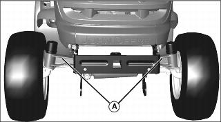
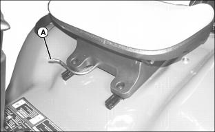
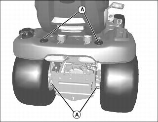
7. Fasten front of machine at both sides of the axle at points (A) to trailer with heavy-duty straps, chains, or cables. Straps must be directed down and outward from machine.
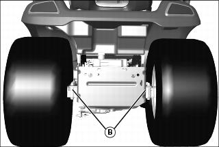
8. Fasten rear of machine at both sides of the axle at points (B) to trailer with heavy-duty straps, chains, or cables. Straps must be directed down and outward from machine.
9. Secure hood to prevent from lifting while driving.
Using Weights
Use weights to improve stability when operating on slopes or using attachments. |
NOTE: See your authorized dealer for recommended weights.
• Install front weights for added stability and steering control when you use equipment such as the rear-mounted grass bagger.
• Install rear weights when using the snow blade or snowblower.
• Remove weights when not required.
Using Tire Chains (X534)
It is recommended to use ballast on the machine to increase traction. However, if chains are desired for winter use, the following procedure must be performed prior to operation with chains:
1. Remove rear wheels. See “Removing and Installing Wheel Assembly” in the “Service, Miscellaneous” section.
Picture Note: Right side shown, steering stop in “normal” position.
2. Remove and retain two M8x30 cap screws (A) and M8 locknuts securing adjustable steering stop (B).
3. Flip steering stop to the “chain” position, with the larger lobe pointed toward the rear axle support casting (C), and secure with M8 hardware, removed earlier. Tighten hardware securely.
This will stop the rotation of the spindle early, preventing chain contact with the frame and other critical components.
When the chains are removed, the stops should be reversed to the “normal” position to allow for full tire rotation and maximum turning performance. Turf operation with the stops in the “chain” position will result in less turning performance and slight scuffing due to imperfect turn geometry.
Using Accessories
Using Heavy Duty CargO Mount™ System
The front and rear Heavy Duty CargO Mount™ brackets (A) can be used for easy attachment of selected optional equipment.
Use John Deere approved optional equipment only. See your Authorized Service Center for approved optional equipment.
Mowing Tips
The following recommendations will produce the best lawn cut quality and appearance:
• Keep mower blades sharp. Dull blades will tear grass; tips of grass will then turn brown.
• Cutting grass too short may kill grass and let weeds grow easily. The suggested finished cut height range is 44 - 70 mm (1.75 - 2.75 in.).
• Adjust cutting height to remove only 1/3 of the grass at a time.
• Mow grass often. Short grass clippings will decay quickly.
• Mow with engine at full throttle.
• Adjust travel speed to match mowing conditions:
• Travel at slow speed when you mow thick, tall grass, make sharp turns or trim around objects.
• Travel at moderate speed when you mow thin grass.
• Use a different mowing pattern each time you mow. Overlap mowing paths 50 - 100 mm (2 - 4 in.).
• Drive over ridges and through shallow ditches straight-on, not at an angle.
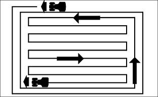
• Mow around the outside twice, then mow inside in straight passes. Best cut is achieved when mowing in a straight line.
• When mowing or mulching near pavement, overlap the pavement by 50 mm (2 in.) to allow clippings to dispense over grass.
• A thick layer of mulched leaves can prevent sunlight from getting to grass and smother it. Taller grass heights allow mulched leaves to dispense easier in lawn. Mulch leaves several times if needed.
• Use a thatcher in late spring or summer to pull up dead grass and aerate ground.
• For Mulching Mower: Shorter cut heights will provide better cut quality, but may leave noticeable clippings. Higher cut heights will reduce clippings, but cut quality may decline.
48C and 54C Blade Choices
Two types of blades are available for X300 and X500 series 3-spindle mowers:
• Side discharge blades. These blades are designed for optimal performance when side discharging and are installed on mowers when shipped from the factory.
• Mulching blades. These blades are designed for optimal performance when used with a mulch kit installed.


