![]()
Introduction
Product Identification
Safety
Operating
Replacement Parts
Service Intervals
Service Lubrication
Service Engine
Service Mower
Replacing Mower Deck Drive Belt
Replacing Primary Drive Belt (SX85)
Replacing Secondary Drive Belt (SX85)
Checking and Adjusting Drive Belt Guides (SX85)
Checking and Adjusting Mower Engagement (PTO) Rod
Checking for Bent Mower Blades
Service Electrical
Service Miscellaneous
Troubleshooting
Storage
Assembly
Specifications
Warranty
John Deere Quality Statement
Service Record

Service Mower
Removing Mower
1. Park machine safely. (See Parking Safely in Safety Section.)
2. Put mower engagement (PTO) lever in the off position.
3. Raise mower deck to 100 mm (4 in).
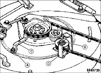
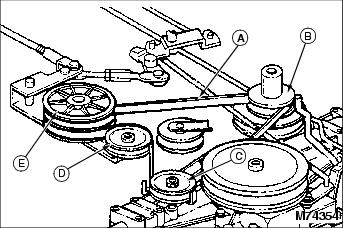
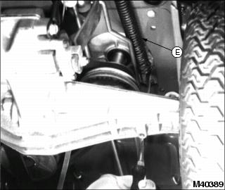
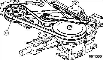
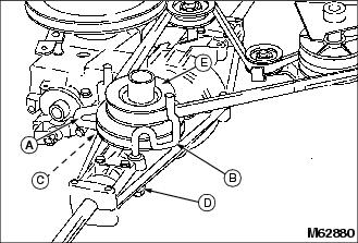
4. Move to rear of tractor and loosen or remove two drive sheave belt guides.
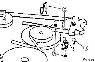
- Remove two nuts (A), carriage bolt (B), and two belt guides (C).

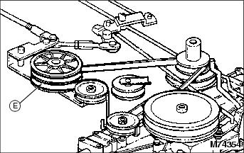
- Loosen nut (D) and move belt guide (E) away from engine sheave.
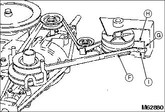
- Remove nut (F) and belt guide (G).
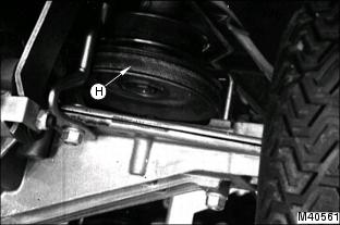
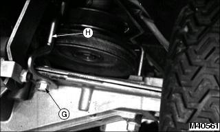
5. Remove drive belt (H) from engine sheave
6. Lower mower deck to 25 mm (1 in).
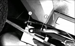
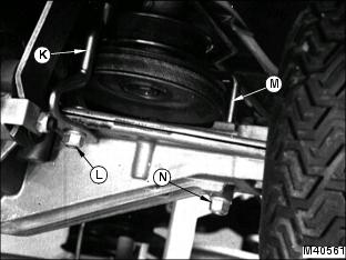
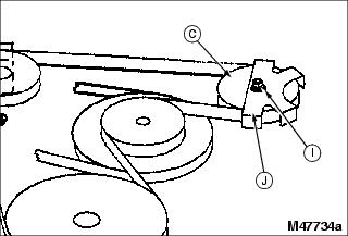
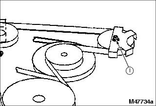
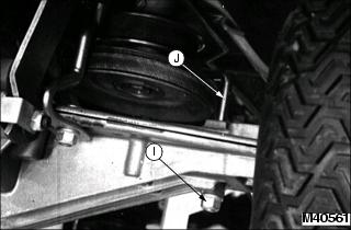
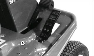
7. Remove spring locking pin (I) and rear draft link (J) from mower lift bracket.
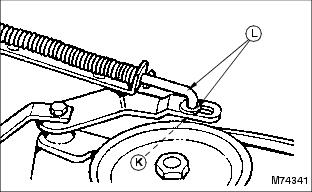
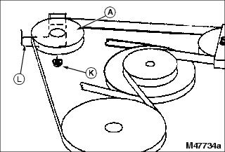
8. Remove spring locking pin and washer (K) and disconnect front of mower engagement (PTO) rod and washer (L) from mower engagement rod arm.
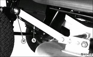
9. Remove spring locking pin and drilled pin (M) and front draft links (N), one on each side of tractor.
10. Turn front wheels fully to the right.
11. Pull mower out from under the left side of tractor.
Installing Mower
1. Park machine safely. (See Parking Safely in the Safety Section.)
2. Put mower engagement (PTO) lever in the off position.
3. Raise mower deck to 100 mm (4 in).
4. Turn front wheels fully to the right.
5. Slide mower under the tractor from left-hand side.

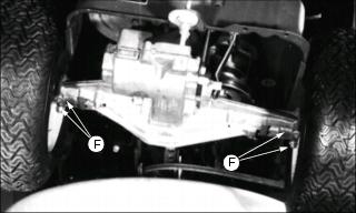
6. Install front draft links (A) to front brackets, one on each side of tractor, with spring locking pins and drilled pins (B).
7. Attach front of mower engagement (PTO) rod and washer (C) to mower engagement rod arm with washer and spring locking pin (D).
8. Lower mower deck to 25 mm (1 in).

9. Install rear draft link (E) to mower lift bracket with spring locking pin (F).
10. Raise mower deck to 100 mm (4 in).
11. Install mower belt (G) on lower part of engine sheave.
IMPORTANT: Avoid damage! The belt will be damaged if belt guides rub against engine sheave. Install belt guides correctly. |
- Install belt guides (H) with carriage bolt (I) and nuts (J). Tighten nuts. Make sure belt guides do not rub against engine sheave.
- Move belt guide (K) against belt and tighten nut (L).
- Install belt guide (M) and nut (N). Tighten nut.
13. Model SX85: Check belt guide clearance and adjust if necessary.
· Clearance between belt guides and upper part of engine sheave should be 1.6-3.2 mm (1/16-1/8 in).
Replacing Mower Deck Drive Belt
NOTE: Mower deck was removed for this procedure but, it is not necessary to remove deck when replacing belt.
1. Park machine safely. (See Parking Safely in the Safety Section.)
2. Remove mower deck from riding mower.

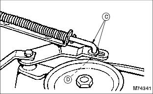
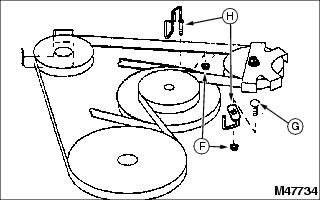
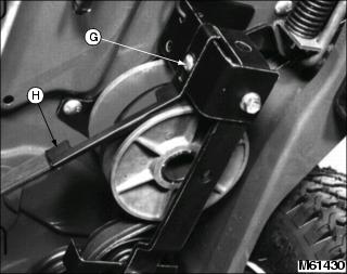
3. Loosen nuts (A) and (B) and rotate belt guides (C) and (D) away from belt.
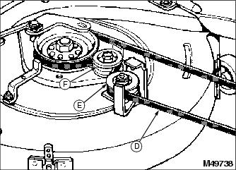
4. Remove mower drive belt (D) from V-idler (E) and flat idler (F).
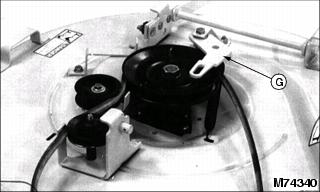
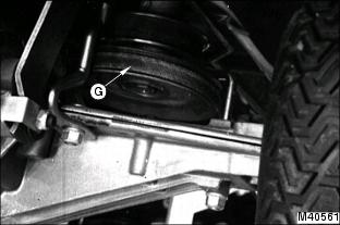
5. Push brake arm (G) inward to relieve spring tension and remove belt from sheave.
6. Clean top of mower deck and sheaves.
7. Inspect belt for wear or damage; replace as necessary.
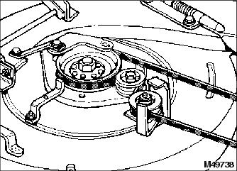
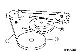
8. Install belt on mower deck as shown.
9. Move belt guides (C) and (D) against belt and tighten nuts (A) and (B).
· Make sure belt to belt guide clearance is approximately 1 mm (1/16 in).
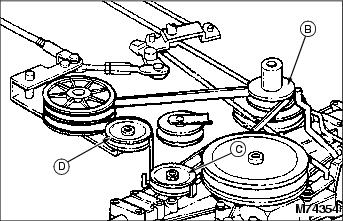
Replacing Drive Belt (GX85)
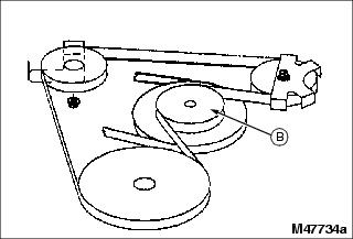
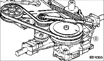
GX85 Transaxle Drive System
B - Jacksheave (Upper engine sheave)
Removing Belt
1. Park machine safely. (See Parking Safely in the Safety Section.)
2. Raise mower deck to 100 mm (4 in).
4. Lift rear of riding mower with safe lifting device and install support stands.
5. Remove two nuts (F), carriage bolt (G) and belt guides (H).
6. Remove drive belt (E) from upper part of engine sheave (B) and drive sheave (D).
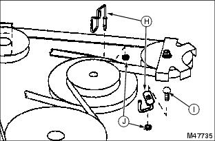
7. Loosen nut (I) on idler (C), move belt guide (J) away from belt and remove belt from idler.
8. Remove nut (K) and remove belt guide (L) and belt from idler (A).
9. Inspect belt for wear or damage; replace as necessary.
Installing Belt
1. Turn belt inside out. Bring belt in from front of riding mower and place belt on upper part of engine sheave (B) with "V" of belt in "V" of engine sheave.
2. Place belt on drive sheave.
3. Place belt under belt guide on idler and tighten nut (I).

4. Place belt around idler, install belt guide and nut (K). Tighten nut.
5. Check that belt is installed on all idlers.
6. Install belts guides on engine sheave.
· Make sure belt guides do not rub against engine sheave.
Replacing Primary Drive Belt (SX85)
SX85 Variator Drive System (Primary Belt)
Removing Belt
1. Park machine safely. (See Parking Safely in the Safety Section.)
2. Raise mower deck to 100 mm (4 in).
4. Lift rear of riding mower with safe lifting device and install support stands.

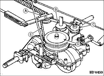
5. Remove secondary spring (F) from riding mower frame.
6. Loosen nut (G) and move rear belt guide (H) away from engine sheave.
7. Remove nut (I) and belt guide (J) and remove mower belt from engine sheave.

8. Loosen nut (K) and move variator belt guide (L) away from primary belt.
9. Remove primary belt from lower sheave of variator (E).
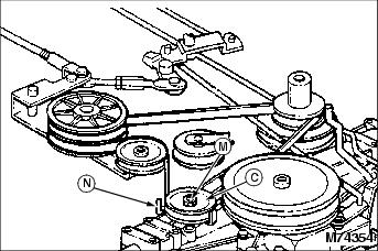
10. Loosen nut (M) and move belt guide (N) away from V-idler (C).
11. Remove belt from primary idler (D), V-idler (C), and engine sheave (B).
12. Inspect belt for wear or damage; replace as necessary.
Installing Belt
NOTE: Before installing Primary Drive Belt, also inspect Secondary Drive Belt for wear or damage and replace it, if necessary.
1. Install belt on sheave and idlers in the following order:
2. Move V-idler belt guide into position and tighten nut.
IMPORTANT: Avoid damage! The belt will be damaged if belt guides rub against sheaves. Install belt guides correctly. |
3. Install variator belt guide as close to belt as possible and tighten nut.
· Check and adjust belt guide if necessary.
4. Install mower belt on lower engine sheave.
5. Install belt guides on engine sheave.
· Check belt guide clearance and adjust if necessary.
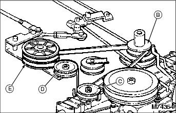
Replacing Secondary Drive Belt (SX85)
SX85 Variator Drive System (Secondary Belt)
Removing Belt
1. Park machine safely. (See Parking Safely in the Safety Section.)
2. Raise mower deck to 100 mm (4 in).
4. Lift rear of riding mower with safe lifting device and install support stands.
5. Remove secondary spring (E).
6. Loosen nuts (F). DO NOT remove nuts. Transaxle should drop slightly.
7. Loosen nut (G) and move variator belt guide (H) away from primary belt and remove primary belt from lower sheave of variator.

8. Remove secondary belt from top sheave of variator (C).
9. Pull belt off rear of transaxle sheave (B) and out left rear corner of riding mower.
10. Inspect belt for wear or damage; replace as necessary.
Installing Belt
1. Install secondary drive belt on top sheave of variator (C).
IMPORTANT: Avoid damage! The belt will be damaged if belt guides rub against sheaves. Install belt guides correctly. |
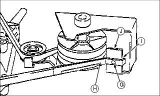
2. Move variator belt guide (H) against primary belt and and fasten with nut (G).
· Check that tab (I) is contacting variator bracket (J) and belt guide is parallel to side and top of belt, but not touching belt.
3. Install secondary belt on transaxle sheave.
4. Install belt on flat idler.
7. Check drive belt guides and adjust if necessary.
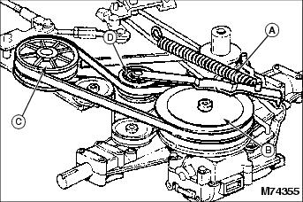
Checking and Adjusting Drive Belt Guides (SX85)
1. Park machine safely, but do not engage park brake. (See Parking Safely in the Safety Section.)
3. Lift rear of riding mower with safe lifting device and install support stands.
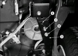
4. Check belt guide to sheave clearance on belt guides (A) and (B) and adjust if necessary.
· Clearance between belt guides and upper part of engine sheave should be 1.6-3.2 mm (1/16-1/8 in).
· Tighten or loosen nuts (C) and (D) to gain clearance. Do not push on jacksheave (E) when moving guides to primary drive belt.
5. Check adjustment of variator belt guide (F).
· Check that tab (G) is contacting variator bracket (H) and belt guide is parallel to side and top of belt, but not touching belt.
· Make sure variator belt is tight and then turn nut (I) to achieve proper adjustment.
· To attain proper adjustment, it may be necessary to bend guide.
6. Operate riding mower to verify adjustments and adjust again, if necessary.
Checking and Adjusting Mower Engagement (PTO) Rod
1. Park machine safely. (See Parking Safely in the Safety Section.)
2. Check that the mower engagement (PTO) rod is properly set:

a. Raise mower to 100 mm (4 in) and push mower engagement (PTO) lever completely forward to position;
Nipples on rod (A) should pull away from PTO bracket (B).
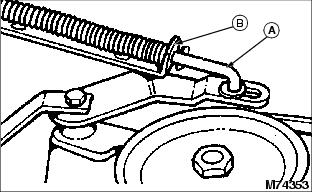
b. Lower mower to 25 mm (1 in) and move mower engagement (PTO) lever completely rearward to position;
Nipples on rod (A) should touch PTO bracket (B).
3. Adjust the mower engagement (PTO) rod, if necessary:
a. Move mower engagement (PTO) lever completely rearward to position.
b. Lower mower to 25 mm (1 in).
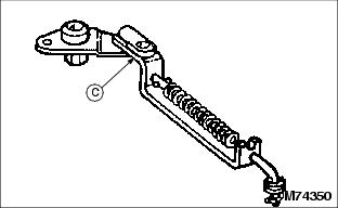
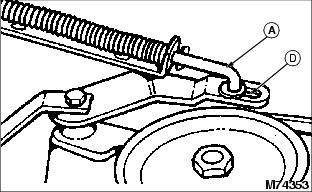
d. Pull engagement rod (A) forward until it is at front of slot (D).
4. Check that mower engagement rod is adjusted properly. PTO engagement rod is in proper adjustment when:
· Nipples pull away from bracket when mower engagement (PTO) lever is completely forward to position and mower is at highest setting, 100 mm (4 in).
NOTE: If the brake arm (E) cannot be adjusted to touch belt when mower engagement (PTO) lever is completely rearward, see your John Deere dealer.
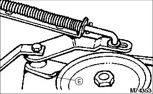
· Brake arm (E) touches belt when mower engagement (PTO) lever is completely rearward to position and mower is at lowest setting, 25 mm (1 in).
Restoring Ground Speed (SX85)
Your (SX85) riding mower ground-speed is pre-set at the factory. However, as the riding mower is used, the primary drive belt will wear and stretch slightly which will restrict your riding mower from obtaining maximum ground-speed. If desired, speed may be restored by following steps listed below.
1. Park machine safely. (See Parking Safely in the Safety section.)
2. Move shift lever (A) to forward position.
3. Check the amount of free play in the accelerator pedal by applying moderate hand pressure to the top of the accelerator pedal until the pedal becomes harder to push.
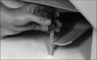
4. Measure distance from accelerator pedal to edge of slot in riding mower platform, dimension (A).
5. Adjust idler arm if dimension (A) equals 38 mm (1-1/2-in.) or more. Do Not adjust idler arm if dimension is less than 38 mm (1-1/2-in.).
b. Loosen bolt (C) in idler arm (D).
c. Push idler arm toward center of unit and install bolt (B) into alternate hole (E).
IMPORTANT: Avoid damage! If riding mower does not Stop, idler arm must be returned to its original position. See your John Deere dealer for any further speed adjustments. |
6. Test adjustment in an open area:
b. Move shift lever to forward position.
c. Drive riding mower forward and remove foot from accelerator pedal. Riding mower must stop. (If mower does not stop, see your John Deere dealer.)
Checking for Bent Mower Blades
1. Park machine safely. (See Parking Safely in the Safety Section).
2. Put lift lever in mowing position.
3. Measure distance between blade tip and flat ground surface.
4. Turn blade. Measure distance between other blade tip and flat ground surface.
5. Install new blade, if the difference between the two measurements is more than 3 mm (1/8 in).
Servicing Mower Blade
Removing Mower Blade
1. Raise mower deck to gain access to mower blades. If necessary, remove mower deck.
2. Block mower blade with a piece of wood to prevent it from spinning.
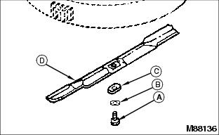
3. Loosen and remove cap screw (A), hardened washer (B), blade washer (C), and blade (D).
4. Inspect blade; sharpen, balance or replace blade as necessary.
Installing Mower Blade
1. Lubricate bolt threads lightly with a general purpose grease or oil. This lubrication is to prevent rusting and seizing.
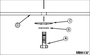
2. Position mower blade (D) with the cutting edge towards the ground onto the mower spindle.
3. Install blade washer (C) with cup side toward the blade, hardened washer (B) and cap screw (A).
4. Tighten cap screw (A) by hand until mower blade is in full contact (fully seated) with spindle.
5. Block mower blade with a piece of wood to prevent spinning, tighten cap screw to 68 - 79 N·m (50 - 58 lb-ft).
Sharpening Blades
Sharpen blades with grinder, hand file, or electric blade sharpener.
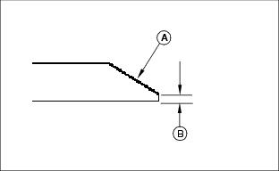
Keep original bevel (A) when grinding.
Blade should have 0.40 mm (1/64 in.) cutting edge (B) or less.
Balance blades before installing.
Balancing Blades
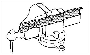
2. Put blade on nail in a vise. Turn blade to horizontal position.
3. Check balance. If blade is not balanced, heavy end of blade will drop.