![]()
Introduction
Product Identification
Safety
Operating
Replacement Parts
Service Intervals
Service Lubrication
Service Engine
Service Mower
Service Electrical
Service Miscellaneous
Troubleshooting
Storage
Assembly
Specifications
Warranty
John Deere Quality Statement
Service Record

Assembly
Check and Connect the Battery
· Wear eye protection and gloves. · DO NOT allow direct metal contact across battery posts. |
NOTE: The battery was filled with acid and charged when it left the factory. To extend battery life, charge the battery prior to delivery.
Do not attempt to open, add fluid or service battery. Any attempt to do so will void the warranty.
1. Check battery voltage, charge if necessary.
· Battery should be charged if voltage is below 12.3 volts. Battery is fully charged at 12.6 volts.
2. Remove and discard the RED positive (+) protective cap from the positive (+) battery terminal.
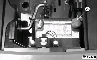
3. Connect positive (+) cable (A) to battery.
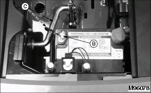
4. Route negative (-) cable (B) under rod (C) and connect negative (-) cable to battery.
5. Apply general purpose grease or silicone spray to terminal to help prevent corrosion.
6. Slide red cover over positive battery cable.
Install Steering Wheel
1. Put front wheels in the straight forward position.
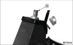
2. Remove steering wheel bolt, washer, and lock nut from steering shaft (A).
3. Put steering wheel on shaft.
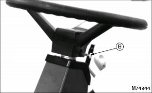
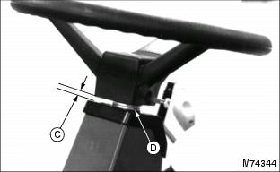
5. Check for steering wheel shaft end play (C) with a feeler gauge. Maximum end play should be equal to or less than 0.635 mm (0.025 in.):
· Pull steering wheel off of shaft.
NOTE: When installing washers on steering wheel shaft, make sure larger washer(s) are put on shaft first.
· Add or remove washer(s) (D) as required.
6. Install steering wheel on shaft.
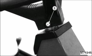
8. Install washer and lock nut (E).
9. Tighten lock nut until it is snug. Do not pull washer or head of bolt into steering wheel.