![]()
Introduction
Product Identification
Safety
Operating
Replacement Parts
Service Intervals
Service Lubrication
Service Engine - Models GX325 and GX335
Service Engine - Model GX345
Service Transmission
Service Steering
Service Mower
Service Electrical
Service Miscellaneous
Troubleshooting
Storage
Assembly
Install Steering Wheel and Tilt Lever
Installing Plastic Front Bumper Cover
Specifications
Warranty
John Deere Quality Statement
Service Record

Assembly
Install Steering Wheel and Tilt Lever
1. Position front wheels to point straight forward.
2. Remove and discard protective cap from steering shaft.
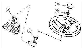
3. Install plastic spacer (A) on steering shaft.
4. Install lever (B) on shaft.
5. Install steering wheel on shaft.
6. Install and tighten nut (C) to 20 N·m (15 lb-ft).
7. Install center cap (D) so leaping deer is positioned properly.
Installing Plastic Front Bumper Cover
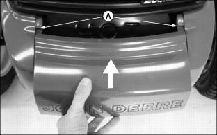
1. Slide bumper cover into slots (A).
2. Push down on front center of cover until it snaps into place.
Install Seat
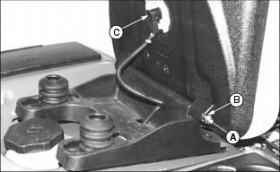
1. Install seat on seat base and install hinge pin (A).
2. Install E-ring (B) onto each end of hinge pin.
Check Tire Pressure
2. Check tire pressure with an accurate gauge.
3. Add or remove air, if necessary.
Charge and Connect Battery
IMPORTANT: Avoid damage! Follow instructions carefully. Battery and battery cables must be installed correctly. When installing battery, make sure battery posts are facing toward front of machine. |
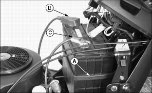
2. Release rubber strap (A) and remove battery.
3. Remove protective caps from battery terminals. Retain the black negative cap.
4. Charge battery. Full charge is 12.6 volts.
5. Install black protective cap over negative (-) terminal.
6. Install battery with terminals toward front of machine. Secure with rubber strap.
IMPORTANT: Avoid damage! To prevent damage to fuel line on models GX325 and GX335, route positive (+) battery cable so it is not between fuel line and engine. |
7. Connect red positive cable (B) to positive (+) battery terminal. Tighten the connection.
8. Apply general purpose grease or silicone spray to terminal to help prevent corrosion. Slide red cover over positive (+) terminal.
9. Remove and discard protective cap from negative (-) battery terminal.
10. Connect black negative cable (C) to negative (-) battery terminal. Tighten the connection.
11. Apply general purpose grease or silicone spray to terminal to help prevent corrosion.
Level Mower Deck
1. Park machine safely on a level surface. (See Parking Safely in the SAFETY section.)
2. Level mower deck side-to-side and front-to-rear.
Install Discharge Chute
NOTE: Attaching hardware is provided in the bag of parts.
1. Install discharge chute to mower deck with two M8x16 bolts (A) and lock nuts (B).
2. Tighten nuts to 20 N·m (15 lb-ft).
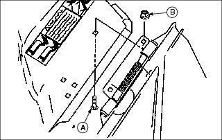
Install Mower Wheels
2. Raise mower deck completely.
3. Park machine safely with mower in raised position. (See Parking Safely in the SAFETY section.)
4. Remove wheels from mower and install in operating position:
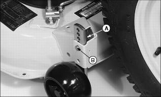
· 48C Mower - Remove spring locking pin (A) and drilled pin (B). Move wheel to operating position. Install pins.
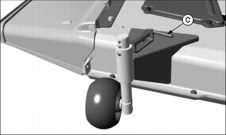
· 54C Mower - Pull pin (C) outward and move wheel to operating position. Release pin to lock wheel in position.
Break-In Electric PTO Clutch
IMPORTANT: Avoid damage! Do not break-in clutch without mower deck installed. Clutch must be burnished against drive resistance of mower deck. |
1. Move machine to a hard, level surface.
4. Lower mower deck completely.
5. Move throttle lever to half speed position. Allow engine to warm 30-60 seconds.
6. Leave throttle at half speed position.
7. Engage PTO and run mower for 5 seconds.
8. Disengage PTO and wait 15 seconds for clutch to cool.
9. Repeat this cycle 15 to 20 times to properly burnish PTO clutch.