![]()
Introduction
Product Identification
Safety
Operating
Avoid Damage to Plastic and Painted Surfaces
Adjusting Mower Level (Side-to-Side)
Adjusting Mower Level (Front-to-Rear)
Testing Reverse Implement Option (RIO)
Using Indicator Lights and Hour Meter
Using the Reverse Implement Option (RIO)
Pushing Machine (Using Free-Wheeling Lever)
Unplugging Mower or Optional Bagger
Transporting Machine on Trailer
Removing and Installing Bumper Cover
Replacement Parts
Service Intervals
Service Lubrication
Service Engine - Models GX325 and GX335
Service Engine - Model GX345
Service Transmission
Service Steering
Service Mower
Service Electrical
Service Miscellaneous
Troubleshooting
Storage
Assembly
Specifications
Warranty
John Deere Quality Statement
Service Record

Operating
Engine Break-In
Poor engine performance can result from improper break-in or incomplete break-in time. Break-in is the period of initial run time that seats the piston rings to the cylinder wall.
New engines need to be run hard, under varying loads for at least 5 hours and may not be completely broken-in until after 50 hours. Follow these guidelines:
· Run engine at full throttle during operation. Use partial throttle only for 30-60 seconds to warm a cold engine.
· Run engine under load by mowing, blowing snow, etc.
· Check oil and coolant (if equipped) levels often. Top off as necessary.
· Follow the break-in service intervals.
Engine may show these symptoms during break-in:
· Excess exhaust smoke at startup and during operation.
· Slight surging at full throttle when not under load.
Daily Operating Checklist
o Check transmission oil level.
o Check coolant level on liquid cooled engine.
o Remove grass and debris from machine.
o Check area below machine for leaks.
Avoid Damage to Plastic and Painted Surfaces
· Do not wipe plastic parts unless rinsed first.
· Insect repellent spray may damage plastic and painted surfaces. Do not spray insect repellent near machine.
· Be careful not to spill fuel on machine. Fuel may damage surface. Wipe up spilled fuel immediately.
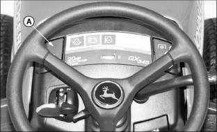
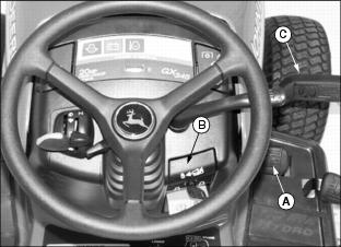
Operator Station
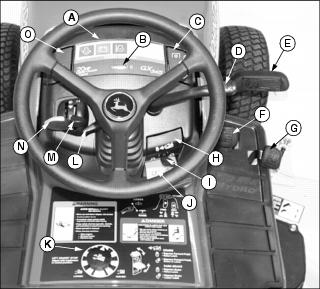
C - PTO Switch / Reverse Implement Option
Miscellaneous Controls
Adjusting Seat
Adjusting Seat Position
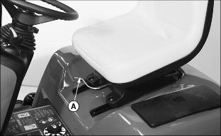
1. Push lever (A) to the left.
2. Slide seat forward or rearward to desired position.
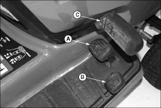
Adjusting Ride Comfort
IMPORTANT: Avoid damage! To prevent damage to seat switch, seat base and fuel tank, do not operate without suspension coils in place. |
2. Rotate suspension coils into desired position:
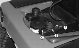
· Move coils to front position (A) for softest ride.
· Move coils to middle position (B) for average ride.
· Move coils to rear position (C) for firm ride.
NOTE: Additional suspension coils can be installed for extra support. See your John Deere dealer.
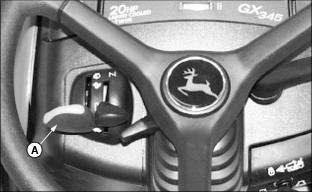
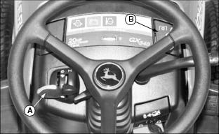
Adjusting Tilt Steering Wheel
· Make sure steering wheel is locked in position before operating machine. |
Steering wheel has five tilt positions:
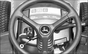
· Pull lever (A) down and move wheel to a comfortable operating position.
· Push lever up to lock wheel in position.
Adjusting Cutting Height
NOTE: Cutting height can be adjusted in 6.25 mm (1/4 in.) increments from approximately 13 to 113 mm (1/2 to 4-1/2 in.).
Mower must be raised completely before turning height control knob.
2. Raise mower deck completely using hydraulic control lever.
3. Park machine safely. (See Parking Safely in the SAFETY section.)
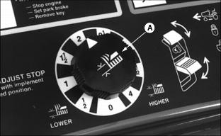
4. Turn mower height control knob (A) to desired cutting height. Mower will be at set cutting height when lowered.
Adjusting Rear Wheel Spacing
NOTE: Wheel spacing is set narrow from the factory. Narrow spacing provides overall tire width of 99.1 cm (39.0 in.). Wide spacing provides overall tire width of 105.4 cm (41.5 in.).
Rear wheels cannot be mounted in wide position if using 48C mower.
1. Park machine safely. (See Parking Safely in the SAFETY section.)
2. Place blocks to the front and rear of the front tires.
3. Loosen the rear wheel bolts.
4. Raise rear of machine with a safe lifting device so rear wheels are slightly off the ground.
5. Remove the rear wheel bolts.
6. Remove rear wheels and install for desired spacing:
Turf Tires
· Narrow Spacing - Install each wheel with valve stem to the outside.
· Wide Spacing - Install each wheel with valve stem to the inside.
Bar Tires
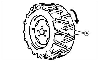
· Narrow or Wide Spacing - Move each wheel to opposite side of machine with traction bars (A) pointing forward.
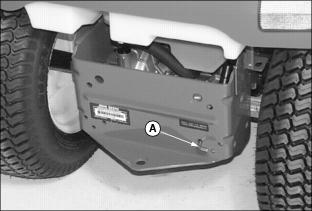
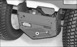
Adjusting Mower Wheels
1. Park machine safely. (See Parking Safely in the SAFETY section).
2. Inflate tires to correct pressure.
4. Raise mower to transport position.
6. Lower mower to cutting position.
8. Measure distance between mower wheels and ground surface. All wheels should be 6-13 mm (1/4-1/2 in.) from ground surface.
NOTE: Mower wheels can be adjusted in 13 mm (1/2 in.) increments. See decal (A) located on deck.
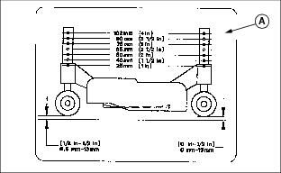
9. Adjust mower wheels to correct height:
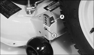
· 48C Mower - Remove spring locking pin (A) and drilled pin (B). Move wheel to proper hole position. Install pins.
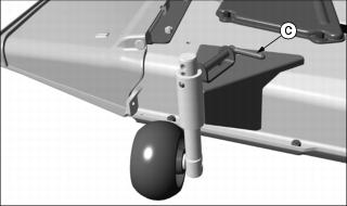
· 54C Mower - Pull pin (C) outward and move wheel to proper hole position. Release pin to lock wheel in position.
Adjusting Mower Level (Side-to-Side)
NOTE: Mower wheels should not contact the ground when leveling the deck.
1. Park machine safely on a level surface. (See Parking Safely in the SAFETY section).
2. Inflate tires to the correct pressure.
3. Adjust cutting height to 50 mm (2 in.).
4. Push hydraulic lift lever forward to lower mower as far as it will go.
NOTE: The difference between blade measurements must not be more than 3 mm (1/8 in.).
5. Turn left blade parallel to axle and complete measurement. Hold drive belt and turn right blade parallel to machine axle and complete measurements.
Picture Note: A convenient leveling gauge (A) is available from your John Deere dealer.
6. Measure from each outside blade tip (B) to the level surface.
NOTE: Cutting height can closely match knob setting by adjusting lift links on both sides of deck.
Picture Note: Left side shown.
7. Adjust lift links, turn nut (C):
· Clockwise to raise left side of mower.
· Counterclockwise to lower left side of mower.
Adjusting Mower Level (Front-to-Rear)
NOTE: Mower wheels should not contact the ground during leveling.
1. Park machine safely on a level surface. (See Parking Safely in the SAFETY section.)
2. Inflate tires to the correct pressure.
3. Adjust cutting height to 50 mm (2 in.).
4. Lower mower deck completely.
5. Turn blades so blade tips point straight forward.
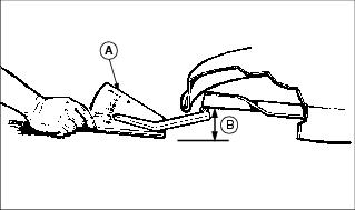
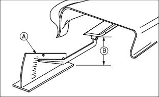
Picture Note: A convenient leveling gauge (A) is available from your John Deere dealer.
6. Measure distance (B) from each blade tip to the surface. The front blade tips must be 3-6 mm (1/8-1/4 in.) lower than rear blade tips.
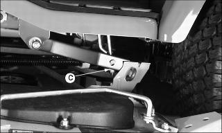
7. Adjust front-to-rear mower level if necessary:
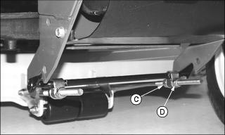
a. Loosen rear nut (C) on each side of front lift rod.
b. Turn front nut (D) on each side clockwise to raise front of mower or counterclockwise to lower it.
c. Tighten rear nuts after adjustment is complete.
8. Check adjustment by measuring blade tips again.
Testing Safety Systems

Use the following checkout procedure to check for normal operation of machine.
If there is a malfunction during one of these procedures, Do not operate machine. See your John Deere dealer for service.
Perform these tests in a clear open area. Keep bystanders away.
Testing Park Brake Switch
1. Park machine safely. (See Parking Safely in the SAFETY section.)
Testing Park Brake
1. Park machine safely. (See Parking Safely in the SAFETY section.)
3. Try to push machine manually.
Testing PTO Switch
1. Park machine safely. (See Parking Safely in the SAFETY section.)
Testing Seat Switch
Test 1
2. Move throttle lever to maximum speed position.
5. Raise up off seat. Do not get off machine.
Test 2
4. Raise up off seat. Do not get off machine.
Test 3
3. Raise up off seat. Do not get off machine.
Testing Reverse Implement Option (RIO)
Before backing up, carefully check the area around the machine. |
1. Park machine safely. (See Parking Safely in the SAFETY section.)
3. Engage PTO to start attachment.
4. Look behind the vehicle to be sure there are no bystanders.
5. Begin reverse travel by depressing reverse foot pedal.
Testing Mower Blade Stop Time
1. Park machine safely. (See Parking Safely in the SAFETY section.)
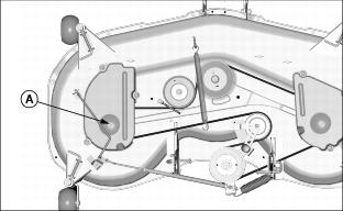
6. Watch left side mower spindle (A). Disengage the PTO.
Using Park Brake
Always lock the park brake and remove the key before leaving the machine unattended. |
Locking Park Brake
1. Push and hold down brake pedal (A).
2. Pull up park brake lever (B) to lock park brake.
3. Release brake pedal. Pedal should stay down and park brake lever should stay up in locked position.
Unlocking Park Brake
1. Push and hold down brake pedal (A).
2. Push down park brake lever (B) to unlock park brake.
3. Release brake pedal. Pedal should come up to operating position.
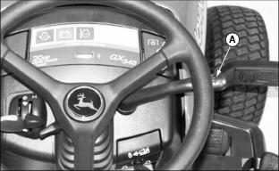
Using Headlights
· Pull up on light handle (A) to turn headlights on.
· Push down on handle (A) to turn headlights off.
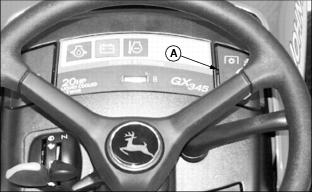
Using Indicator Lights and Hour Meter
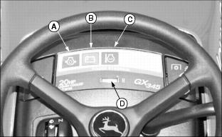
A - Oil Pressure Indicator - will come on when you turn the key to the run position. Indicator should go out when engine is started. If indicator comes on during operation, engine oil pressure is too low. Stop engine and perform appropriate service.
B - Battery Discharge Indicator - will come on when you turn the key to the run position. Indicator should remain on during starting cycle. If indicator comes on during operation, stop engine and perform appropriate service.
C - Coolant Temperature Indicator (Model GX345 Only) - will not come on when you turn the key to the run position. If indicator comes on during operation, coolant temperature is above normal operating temperature. Stop engine and perform appropriate service. Coolant light will come on momentarily when key is turned to the start position.
D - Hour Meter - shows the number of hours the engine has run. The hour meter will operate when key is in the run position with the operator's seat occupied or the park brake locked. Use the hour meter to determine when your machine has reached the recommended service intervals.
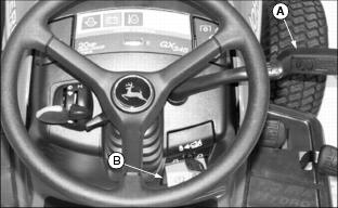
Checking Fuel Level
Check fuel level in fuel tank (A).
Starting the Engine
NOTE: Engine will not start unless park brake is applied and PTO is disengaged.
2. Make sure PTO switch is disengaged.

· If engine is cold, move throttle lever (A) between the half throttle and fast throttle positions.
· If engine is warm, move throttle lever (A) to slow throttle position.
· If engine is cold, push and hold choke lever (B) all the way up to the choke position.
· If engine is warm, push and hold choke lever (B) half way up or do not use at all depending on engine temperature.
6. Turn key to run position (C).
7. Make sure the oil pressure and battery discharge indicators illuminate.
IMPORTANT: Avoid damage! Starter may be damaged if operated longer than 20 seconds at a time. Wait two minutes between starting intervals if engine does not start immediately. |
8. Turn key to start position (D) for no more than 5 seconds.
9. Release key to run position (C) and release choke lever when engine starts. If engine does not start:
b. Hold choke lever in the choke position.
c. Turn key to start position again for no longer than 5 seconds. Release key and choke lever when engine starts.
d. Repeat procedure if necessary.
IMPORTANT: Avoid damage! Unnecessary engine idling can cause engine overheating, carbon build-up, and poor performance. |
10. Run engine at half throttle for 30-60 seconds to allow warm-up before operating.
Stopping the Engine
2. Move throttle lever (A) to the slow position. Allow engine to idle for several seconds.
3. Turn key to stop position (B).
Using Travel Controls
Forward Travel
3. Push down slowly on forward pedal (A) until desired travel speed is obtained.
4. Release forward pedal and machine will automatically return to neutral and stop.
Reverse Travel
NOTE: Any operating attachment will stop as the reverse foot pedal is depressed with attachment engaged.
2. Push PTO knob down to the off position to disengage attachment.
3. Look behind the machine to be sure there are no bystanders nearby.
4. Push down slowly on reverse pedal (B).
Stopping
1. Release either travel pedal, machine will automatically return to neutral and stop.
Using the Reverse Implement Option (RIO)
NOTE: Operating the mower while backing up is strongly discouraged. The Reverse Implement Option should be used only when operating another attachment or when the operator deems it necessary to reposition the machine with the mower engaged.
1. Stop the machine. Allow attachment to run.
2. Look behind the machine to be sure there are no bystanders.
3. Lift PTO switch (A) past the PTO engagement position while depressing reverse foot pedal slightly.
NOTE: If the attachment stops while positioning the machine, return PTO switch to off position. Repeat this procedure from the beginning.
4. As the machine begins to move backward, release the PTO switch and position the machine.
5. Resume forward travel. The attachment should continue operating.
6. Repeat procedure to position the machine again.
Using Cruise Control
Do not use cruise control when going down hills. Machine speed will increase. Operate machine in a large, open area to learn how the cruise control works. |
Use cruise control when you want to maintain travel speed without having to hold the forward travel pedal down. Cruise control operates only for forward travel.
Engaging Cruise Control
1. Push forward pedal (A) down until you reach desired travel speed.
3. Remove foot from forward pedal.
Disengaging Cruise Control
NOTE: Cruise control will also disengage if forward travel pedal is pressed.
Using Hydraulic Control Lever
NOTE: Do not use hydraulic control lever to adjust cutting height of mower deck. Use height control dial for cut height adjustment.
Use hydraulic control lever (A) to raise attachment:
· Pull and hold back lever until attachment is raised.
· Push lever forward to lower attachment.
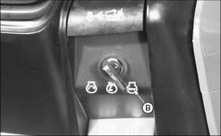
Using PTO (Power Take-Off)
NOTE: PTO operation will stop if reverse pedal is depressed. Understand the Reverse Implement Option (RIO) system before operating the PTO.
1. Start the engine. If necessary, allow engine to warm up before operating PTO.
NOTE: Always operate at maximum throttle speed when PTO is engaged.
2. Move throttle lever (A) to fast position.
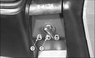
3. Move PTO switch (B) to desired position:
· Engage PTO - Lift up on switch lever to "l" position.
· Disengage PTO - push down on switch lever to "O" position.
· Maintain PTO engagement in reverse - Lift and hold switch lever in the highest position.
Mower Blade Selection
· Standard Blades - Standard blades are designed for bagging, side discharging and all mowing conditions.
· Mulching Blades - Mulching blades are to be used with the optional Mulch Kit.
Pushing Machine (Using Free-Wheeling Lever)
IMPORTANT: Avoid damage! Transmission damage may occur if the machine is moved incorrectly: |
2. Pull out on free-wheeling lever (A).
3. Push machine to desired location.
NOTE: The free-wheeling lever will return to operating position when brake pedal is pressed.
Unplugging Mower or Optional Bagger
· Park the machine safely and lock the park brake before getting off the seat. |
3. Move throttle lever to slow position.
8. Wait for all moving parts to stop.
Transporting Machine on Trailer
Be sure trailer has all the necessary lights and signs required by law.
1. Park trailer on a level surface.
2. Drive forward onto heavy-duty trailer with sides.
3. Lower mower to trailer deck.
5. Fasten machine to trailer with heavy-duty straps, chains, or cables. Both front and rear straps must be directed down and outward from machine.
Removing and Installing Bumper Cover
Remove bumper cover to install suitcase weights and front attachments as necessary. Install bumper cover when front weights or attachments are not in use.
Removing Cover
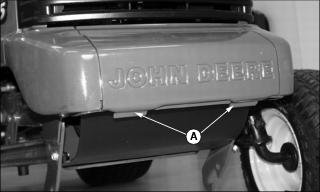
1. Pull back on tabs (A) to release cover.
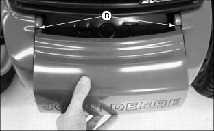
2. Slide cover away from slots (B).
Installing Cover
1. Slide bumper cover into slots (B).
2. Push down on front center of cover until it snaps into place.
Using Weights
Use weights to improve stability when operating on slopes or using attachments. |
Suitcase Weights
NOTE: Up to four suitcase weights can be installed at front or rear of machine to counterbalance front or rear attachments. Each suitcase weight weighs 19 kg (42 lb). Remove weights when not required.
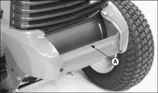
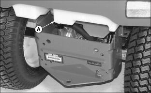
To install suitcase weights at front of machine, remove front bumper. Install weights as necessary on weight bracket (A).
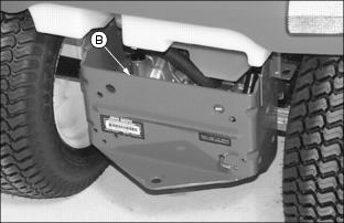
To install suitcase weights at rear of machine, hang weights as necessary over rear frame (B).
Wheel Weights
NOTE: Tire valve stems must be facing to the inside before installing wheel weights. Each front wheel weight weighs 14 kg (30 lb). Each rear wheel weight weighs 23 kg (50 lb). Remove weights when not required.
Install wheel weights using the instructions provided with your weights.
Installing Tire Chains
IMPORTANT: Avoid damage! Loose tire chains can cause machine damage. Periodically check chain tightness and adjust as necessary. |
NOTE: Chains are available from your John Deere dealer.
1. Park machine safely. (See Parking Safely in the SAFETY section.)
2. Lay chains out flat with the cross chain hook ends facing downward.
3. Remove any twists and tangles from cross chain and rim chain.
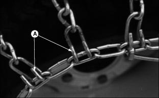
5. Drape chain over tire with the lever fastener on outside of tire and cross link hooks (A) facing upward and away from tire.
6. Adjust chain for straightness and an even amount of cross chain links on each side of tire.
7. Place the first cross chain (opposite the end with fastener and inside hook) under tire.
8. Pull the inside rim chain tight and hook the inside hook.
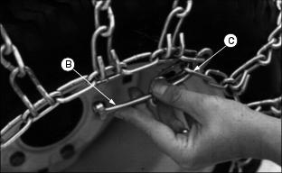
9. Pull the outside rim chain tight and hook the outside lever fastener (B) by running the end through a free link (C).
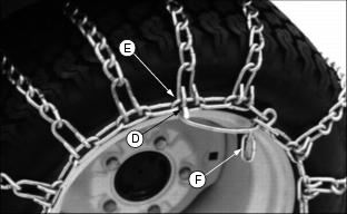
10. Close the fastener by rotating it back 180° and engaging the hook (D) on the end of the fastener into a rim chain link (E).
Make sure the chain is centered on the tire with approximately the same number of free rim links (F) on the inside and outside.
NOTE: The chain should be as tight as possible. If chain is loose, unhook the fastener and pull chain tight again.
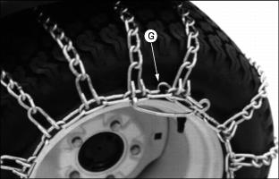
11. Tie excess rim chain links (G) back to the rim chain.
12. Drive forward on chains 9-12 m (30-40 ft.) and recheck for tightness. Adjust as necessary.
Mowing Tips
The following recommendations will produce the best lawn cut quality and appearance:
· Keep mower blades sharp. Dull blades will tear grass; tips of grass will then turn brown.
· Cutting grass too short may kill grass and let weeds grow easily. The suggested finished cut height range is 44-70 mm (1-3/4 to 2-3/4 in.).
· Adjust cutting height to remove only 1/3 of the grass at a time.
· Mow grass often. Short grass clippings will decay quickly.
· Mow with engine at full throttle.
· Adjust travel speed to match mowing conditions:
· Travel at slow speed when you mow thick, tall grass, make sharp turns or trim around objects.
· Travel at moderate speed when you mow thin grass.
· Use a different mowing pattern each time you mow. Overlap mowing paths 50-100 mm (2-4 in).
· Drive over ridges and through shallow ditches straight-on, not at an angle.
· A thick layer of mulched leave can prevent sunlight from getting to grass and smother it. Taller grass heights allow mulched leaves to dispense easier in lawn. Mulch leaves several times if needed.
· Use a thatcher in late spring or summer to pull up dead grass and aerate ground.