![]()
Introduction
Product Identification
Safety
Operating
Replacement Parts
Service Intervals
Service Lubrication
Service Engine
Service Transmission
Service Electrical
Checking Battery Electrolyte Level (Maintenance-Type Battery)
Removing and Installing Battery
Cleaning Battery and Terminals
Replacing Instrument Panel Light Bulb
Service Miscellaneous
Troubleshooting
Storage
Assembly
Specifications
Warranty
John Deere Quality Statement
Service Record

Service Electrical
Battery Statement
Service the Battery Safely

Checking Battery Electrolyte Level (Maintenance-Type Battery)
NOTE: Add only distilled water to replace normal electrolyte loss.
1. Park the vehicle safely. (See Parking Safely in the SAFETY section.)
2. Remove battery from vehicle and set it on a level surface.
3. Remove battery cell caps. Make sure cap vents are not plugged.
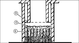
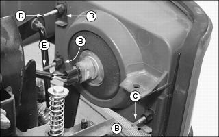
4. Check electrolyte level. Electrolyte (C) should be approximately halfway between bottom of filler neck (D) and top of plates (E).
IMPORTANT: Avoid damage! Do not overfill battery. Electrolyte can overflow when battery is charged and cause damage. |
5. Add only distilled water if necessary.
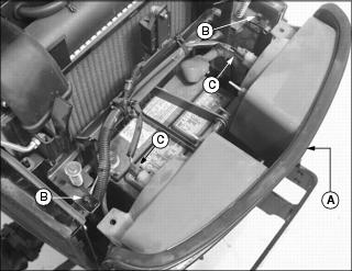
Removing and Installing Battery
Removing
1. Park the machine safely. (See Park Safely in the SAFETY section.)
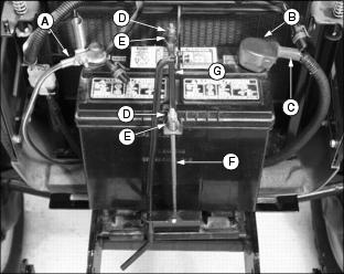
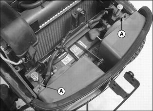
4. Disconnect black negative (-) cable (A) from battery first.
5. Slide red positive terminal cover (B) back and disconnect red positive (+) cable (C).
6. Remove battery hold-down assembly.
· Remove hex nuts (D), bushings (E), threaded rods (F) and bracket (G)
Installing
1. Install battery into tractor.
2. Check manifold caps to be sure vent holes are open.
3. Connect positive (+) cable to battery first, then negative (-) cable.
4. Apply petroleum jelly on battery terminals to help prevent corrosion.
5. Install battery hold-down assembly. Do not overtighten.
Cleaning Battery and Terminals
1. Disconnect and remove battery.
2. Wash battery with solution of four tablespoons of baking soda to one gallon of water. Be careful not to get the soda solution into the cells.
3. Rinse the battery with plain water and dry.
4. Clean terminals and battery cable ends with wire brush until bright.
5. Apply petroleum jelly or silicone spray to terminal to prevent corrosion.
Using Booster Battery
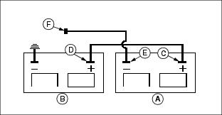
1. Connect positive (+) booster cable to booster battery (A) positive (+) post (C).
2. Connect the other end of positive (+) booster cable to the disabled vehicle battery (B) positive (+) post (D).
3. Connect negative (-) booster cable to booster battery negative (-) post (E).
4. Connect the other end (F) of negative (-) booster cable to a metal part of the disabled machine frame away from battery.
5. Start the engine of the disabled machine and run machine for several minutes.
6. Carefully disconnect the booster cables in the exact reverse order: negative cable first and then the positive cable.
Replacing Fuses
IMPORTANT: Avoid damage! The electrical system may be damaged if incorrect replacement fuses are used. Replace the bad fuse with a fuse of the same amp rating. |
1. Park machine safely. (See Parking Safely in the SAFETY section.)
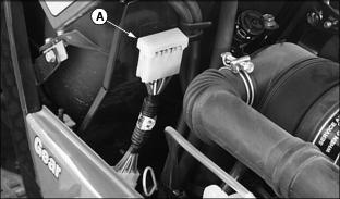
3. Squeeze ends of fuse holder cover (A) to remove.
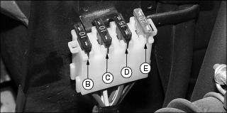
5. Pull defective fuse from socket.
Replacing Headlight Bulb
IMPORTANT: Avoid damage! Do not touch glass headlight bulb with bare skin or bulb may fail prematurely. Use gloves or a cloth when inspecting or replacing the bulb. |
1. Park machine safely. (See Parking Safely in the SAFETY section.)
3. Remove clips holding front grille to frame.
4. Carefully remove grille (A) from mounting studs (B). Move top of grille forward.
5. Disconnect wire harness (C) from defective headlight bulb assembly.
6. Rotate bulb assembly to remove from housing socket.
7. Install new bulb assembly into housing socket and rotate to lock in place.
8. Connect wire harness to bulb assembly.
9. Check operation of headlights.
Replacing Taillight Bulb
NOTE: Taillight can be serviced by removing the rear assembly lens only. Warning light can be serviced by removing the front or rear assembly lens.
1. Park machine safely. (See Parking Safely in the SAFETY section.)
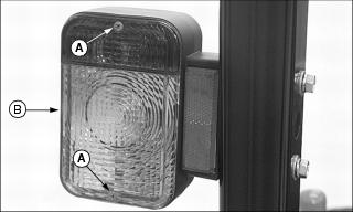
2. Remove two screws (A) and lens (B) from the warning light/taillight assembly.
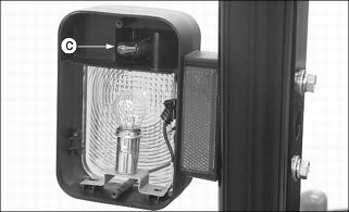
3. Pull bulb (C) to remove. Do not twist bulb.
5. Check operation of taillights.
Replacing Warning Light Bulb
NOTE: Warning light can be serviced by removing the front or rear assembly lens.
Light assembly on left side of ROPS is a combination warning light/taillight.
1. Park machine safely. (See Parking Safely in the SAFETY section.)
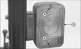
2. Remove two screws (A) and lens (B) from warning light assembly.
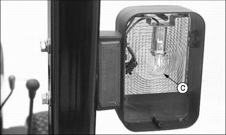
3. Push down and rotate bulb (C) to remove.
4. Push new bulb into socket and rotate to lock in place.
5. Check operation of warning lights.
Replacing Instrument Panel Light Bulb
1. Park machine safely. (See Parking Safely in the SAFETY section.)
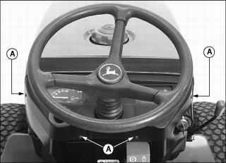
2. Remove four screws (A) from instrument panel housing. Carefully move housing rearward.
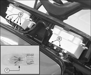
3. Identify defective bulb location.
4. Remove bulb holder (B) from instrument panel socket. Do not twist.
5. Push new bulb (C) into socket.
6. Install bulb holder into instrument panel.
8. Install instrument panel housing.
Adjusting Head Lights
1. Park machine safely on a level surface at least 5m (15 ft) away from a flat vertical surface. (See Parking Safely in the SAFETY section.)
5. Carefully remove grille from mounting studs. Move top of grille forward.
NOTE: Do not remove clips (B) when making a head light adjustment.
6. Adjust head lights to a desirable operating position:
· Turn screw (C) counterclockwise or screw (D) clockwise to adjust light beam up.
· Turn screw (C) clockwise or screw (D) counterclockwise to adjust light beam down.
· Turn screw (E) clockwise to adjust light beam toward center of tractor or counterclockwise to adjust light beam away from center of tractor.