![]()
PIN TC1420G010001, TC1435D010001, TC1445D010001
Introduction
Product Identification
Safety
Operating Machine
Replacement Parts
Service Intervals
Service Lubrication
Service Engine
Service Transmission
Service Steering & Brakes
Steering Column Tilt-Lock Adjustment
Service Electrical
Service Miscellaneous
Troubleshooting
Storage
Assembly
Specifications
Warranty
John Deere Quality Statement
Service Record
Copyright© Deere & Company

Service Steering & Brakes
Adjusting Toe-In
1. Park the machine safely. (See Parking Safely in the Safety section.)
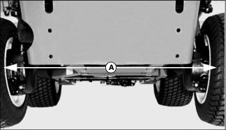
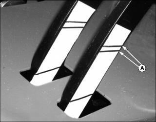
2. Measure the distance (A) between the rear tires at the rear of tires.
3. Measure the distance between rear tires at front of tires.
4. Distance between tires (toe-in) should be 3-9 mm (0.12-0.35 in.) less in front than in rear.
5. If toe-in requires adjustment, proceed as follows:
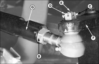
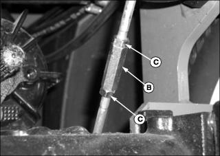
a. Loosen lock nuts (B) on left and right side of tie-rod ends. (Left side lock nut has left-hand threads.)
b. Remove the cotter key (C) from tie-rod castle nut (D) and remove nut.
c. Remove tie-rod mounting stud (E) from the steering arm (F).
d. Turn body of tie-rod (G) to adjust toe-in, keeping tie-rod mounting stud upright while turning tie-rod.
e. Install tie-rod stud into steering arm and loosely install castle nut onto stud.
f. Measure toe-in again. If correct, tighten castle nut and install cotter key. Tighten lock nuts on left and right side of machine.
Adjusting Brakes
Checking Brake Pedal Free Play
1. Park machine safely on level ground. (See Parking Safely in the Safety section.)
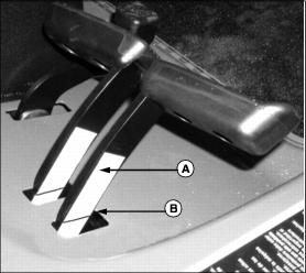
3. Place a piece of masking tape (A) on the side of the turn brake arm, so that the lower end of the tape extends below the operator's platform.
4. With no pressure on the pedal, make a mark (B) at the same height as the operator's platform on the masking tape.
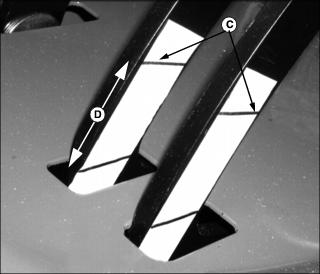
5. Press the turn brake pedal until the brake engages, and mark the position of the operator's platform on the tape (C).
6. Release the brake pedal and measure the distance between the front edge of the marks on the tape (D) to determine the brake pedal travel.
7. Repeat steps 3-6 for the other turn brake pedal.
8. If brake pedal travel is greater that 30mm, the brakes require adjustment.
Adjusting Brakes
1. Using the masking tape installed earlier, make two marks (A) at 25mm and 30mm above the operator's platform level.
2. Locate the adjustment turnbuckles (B) on the brake rods under the operator's platform.
3. Loosen the lock nuts (C), and adjust the turnbuckles until the brake begins to engage when the pedal is between the 25mm and 30mm marks on the masking tape.
4. Repeat for other pedal, keeping left and right side pedals adjusted evenly.
5. Tighten all turnbuckle lock nuts.
6. If brakes cannot be adjusted within the range of the turnbuckles, see your John Deere Dealer.
Steering Column Tilt-Lock Adjustment
1. Park machine safely. (See Parking Machine Safely in the Safety section.)
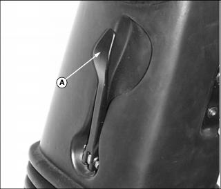
2. Pull lever (A) outward to release steering column.
3. Push steering wheel forward or rearward to center steering column in its travel range.
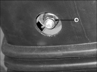
4. Torque M12 nylock nut (B) on right side of steering column to 20-27 N·m (15-25 ft-lb). (Do not exceed 48 N·m (35 ft-lb) or damage may occur.)