![]()
PIN TC1420G010001, TC1435D010001, TC1445D010001
Introduction
Product Identification
Safety
Operating Machine
Replacement Parts
Service Intervals
Service Lubrication
Service Engine
Service Transmission
Service Steering & Brakes
Service Electrical
Service Miscellaneous
Troubleshooting
Storage
Assembly
Checking Tire Inflation Pressure
Specifications
Warranty
John Deere Quality Statement
Service Record
Copyright© Deere & Company

Assembly
Opening Shipping Container
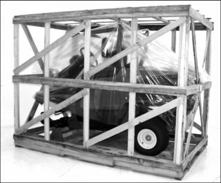
1. Place shipping container on flat, level surface, with enough room to work safely with large boards. Remove boards from work area immediately after dismantling to prevent injuries from falls, nails, and splinters.
2. Using a large pry bar and hammer, pry top of shipping container up from sides. Remove top.
3. Pry apart sides of shipping container at corners and allow sides to drop to floor. Remove sides from bottom.
4. Remove plastic sheathing from machine.
IMPORTANT: Avoid damage! If using an overhead hoist to raise front of machine, do not hook to steering wheel, operator's platform, or any other location that is not a part of the structural frame! |
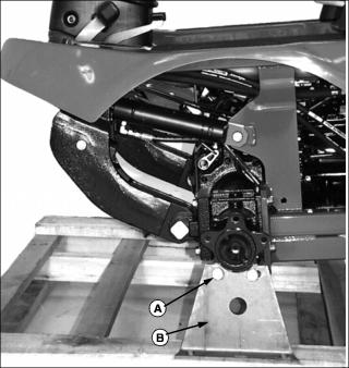
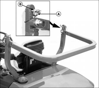
5. Using a floor jack under the front transaxle housing, take the weight off of the front axle until the lug bolts and washers (A) can be removed from the shipping brackets (B).
6. Remove four lug bolts and washers from left and right side front axle.
7. Remove shipping brackets from left and right side of shipping container.
8. Lift front of machine high enough to install front wheels.
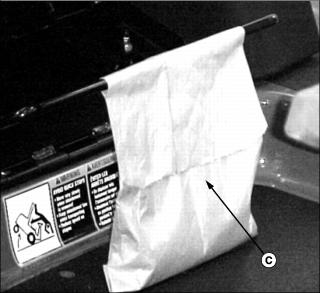
9. Locate bag of parts (C) from operator's seat adjustment lever. Remove bag from machine and take out six lug bolts and six lock washers.
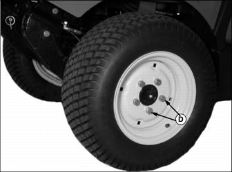
10. Using lug bolts and washers from bag of parts and shipping brackets, install front tires onto front axle and torque bolts to 225 N·m (165 lb-ft).
11. Lower machine off of floor jack.
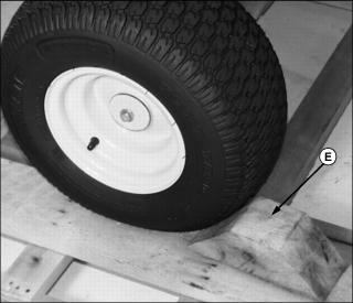
12. Using a pry bar and hammer, remove the wheel blocks (E) from behind the left and right side rear tires.
Checking Tire Inflation Pressure
1. Set tire inflation to following pressures:
· Front Tires: 140 kPa (20 psi)
· Rear Tires: 140 kPa (20 psi)
Raising ROPS
1. Remove spring pin (A) from drilled pin (B) on left and right side of ROPS.
2. Remove drilled pin from left and right side of ROPS.
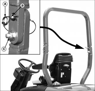
3. Push ROPS into upright position.
4. Install drilled pin into holes on left and right side of ROPS, and secure in place with spring pins.
5. Tighten the ROPS attaching bolts (C) to 40 N·m (30 lb-ft).
Connecting Battery Cables
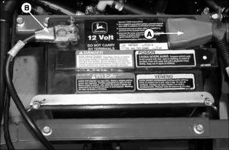
1. Install positive (+) battery cable clamp (A) (red cable) onto right side positive (+) battery post. Tighten clamp and install red cover as shown.
2. Install negative (-) battery cable clamp (B) (black cable) onto left side negative (-) battery post. Tighten clamp.