![]()
PIN TC1420G010001, TC1435D010001, TC1445D010001
Introduction
Product Identification
Safety
Operating Machine
Replacement Parts
Service Intervals
Service Lubrication
Service Engine
Service Transmission
Service Steering & Brakes
Service Electrical
Checking Battery Electrolyte Level
Removing and Installing the Battery
Cleaning Battery and Terminals
Service Miscellaneous
Troubleshooting
Storage
Assembly
Specifications
Warranty
John Deere Quality Statement
Service Record
Copyright© Deere & Company

Service Electrical
Battery
Checking Battery Electrolyte Level
1. Remove battery manifold caps.
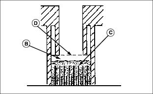
2. Check electrolyte level. Electrolyte level (B) should be 6 mm (1/4 in.) above plates (C) and below filler neck (D).
3. Add distilled water if necessary.
Removing and Installing the Battery
Removing:
1. Park machine safely. (See Parking Safely in the Safety section.)
2. Raise the operator's seat platform.
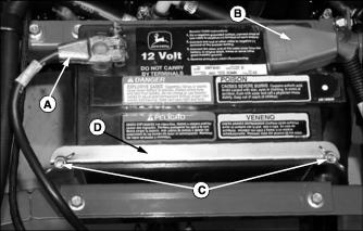
3. Disconnect negative (-) battery cable (A).
4. Pull up red plastic cover (B) from positive (+) battery clamp and disconnect positive (+) cable clamp from battery post.
5. Remove wing nuts (C) from left and right side of battery hold down bracket (D).
6. Remove battery from machine. Do not use battery terminals to lift battery.
Installing:
1. Install battery with positive post (+) on right side of machine.
2. Install battery J-bolts, hold down bracket, and secure with wing nuts.
3. Install positive cable clamp (red cable) onto positive (+) battery post. Pull red plastic cover over positive cable clamp.
4. Install negative cable clamp (black cable) onto negative (-) battery post.
5. Lower operator's seat platform.
Cleaning Battery and Terminals
1. Disconnect and remove battery.
2. Wash battery with solution of four tablespoons of baking soda to one gallon of water. Be careful not to get the soda solution into the cells.
3. Rinse the battery with plain water and dry.
4. Clean terminals and battery cable ends with wire brush until bright.
6. Attach cable clamps to battery posts.
7. Apply petroleum jelly or silicone spray to terminal to prevent corrosion.
Using Booster Battery

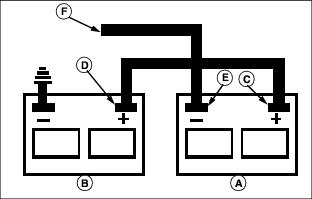
1. Connect positive (+) booster cable to booster battery (A) positive (+) post (C).
2. Connect the other end of positive (+) booster cable to the disabled vehicle battery (B) positive (+) post (D).
3. Connect negative (-) booster cable to booster battery negative (-) post (E).
4. Connect the other end (F) of negative (-) booster cable to a metal part of the disabled machine frame away from battery.
5. Start the engine of the disabled machine and run machine for several minutes.
6. Carefully disconnect the booster cables in the exact reverse order: negative cable first and then the positive cable.
Checking and Replacing Fuses
Main Fuse Replacement
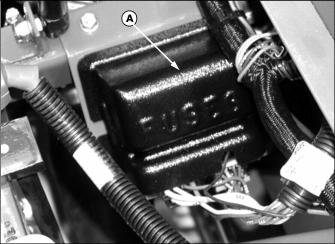
2. Locate the electrical control box (A) on the right side of the engine compartment.
3. Remove cover (A) from panel.
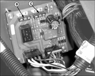
4. Fuse (B) is a 15 amp fuse and controls all lights on the machine.
5. Fuse (C) is a 15 amp fuse and controls all other electrical functions
6. Test fuses with voltmeter or test lamp and replace if burned out.
Radiator Fan Fuse Replacement
1. Park machine safely. (See Parking Safely in the Safety section.)
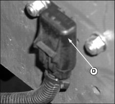
3. Locate the radiator fan fuse (D) on the right side of engine compartment.
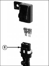
4. Pull out lock tab (E) and pull base of fuse holder down from cap.
5. Test fuse using a voltmeter or test lamp. Both sides of fuse should be hot (even with key switch in off position).