![]()
PIN TC1420G010001, TC1435D010001, TC1445D010001
Introduction
Product Identification
Safety
Operating Machine
Replacement Parts
Service Intervals
Service Lubrication
Service Engine
Engine Warranty Maintenance Statement
Raising and Lowering the Seat Platform
Changing Engine Oil and Filter
Cleaning Oil Cooler and Radiator
Checking Air Filter Restriction Indicator
Servicing Air Cleaner Elements
Cleaning Rubber Dust Unloading Valve
Checking Air Intake Hoses and Clamps
Checking Radiator Hoses and Clamps
Servicing Gasoline Fuel Filter
Servicing Spark Plugs (Gasoline Engine)
Checking and Adjusting Alternator Belt
Service Transmission
Service Steering & Brakes
Service Electrical
Service Miscellaneous
Troubleshooting
Storage
Assembly
Specifications
Warranty
John Deere Quality Statement
Service Record
Copyright© Deere & Company

Service Engine
Engine Warranty Maintenance Statement
Maintenance, repair, or replacement of the emission control devices and systems on this engine, which are being done at the customers expense, may be performed by any non-road engine repair establishment or individual. Warranty repairs must be performed by an authorized John Deere dealer.
Avoid Fumes
· If it is necessary to run an engine in an enclosed area, use an exhaust pipe extension to remove the fumes. |
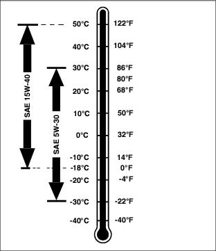
Engine Oil
Use oil viscosity based on the expected air temperature range during the period between oil changes.
Diesel Engines
Other oils may be used if above John Deere oils are not available, provided they meet the following specifications:
· API Service Classification CF or higher.
Gasoline Engines
Other oils may be used if above John Deere oils are not available, provided they meet the following specifications:
· API Service Classification SG or higher.
Engine Cover Operation
1. Park machine safely. (See Parking Safely in the Safety section).
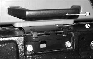
2. Push down on the top of the engine cover latch (A), then pull rearward on the handle (B).
3. Pull the engine cover rearward by the handle until it reaches the end of its travel.
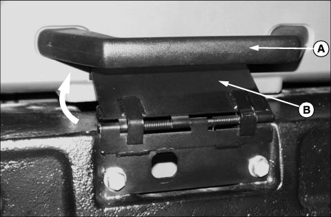
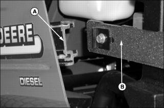
1. Slide the engine cover forward using the handle (A), until the engine cover latch (B) pops up into the locked position shown above.
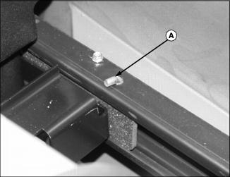
2. Remove pin (A) from left and right side of engine cover slides.
3. Pull engine cover rearward until it can be removed from machine.
Installing the engine cover:
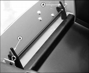
1. Line up slides (A) on inside of engine cover with rails (B) on left and right side of machine.
2. Push the engine cover onto the rails until top edge of engine cover is over radiator cap.
3. Install stop pins into holes on left and right side engine cover slides.
Raising and Lowering the Seat Platform
Raising the seat platform:
1. Pull forward on the release lever (A), while pulling forward on the backrest of the operator's seat.
· The seat platform will raise until the gas strut extends and latches in the open position.
Lowering the seat platform:
1. Push in the lock lever (A) on the gas strut.
2. Pull rearward on the seat backrest until the seat platform lowers and latches.
Checking Engine Oil Level
1. Park machine safely. (See Parking Safely in the Safety section.)
2. Tilt operator's seat platform forward.
3. Remove dipstick (A) located on the left side of the engine. Wipe dipstick with a clean cloth.
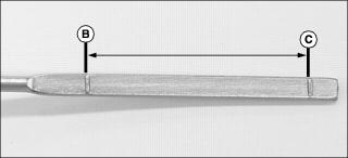
4. Install dipstick, then remove again. Check oil level. Oil should be between levels (B) and (C) on the dipstick.
· If oil is low, add oil to bring oil level no higher than level (B) on the dipstick.
· If oil is above level (B) on the dipstick, drain to proper level.
6. Lower operator's seat platform.
Changing Engine Oil and Filter
2. Park machine safely. (See Parking Safely in the Safety section.)
4. Place a drain pan under the oil drain location.
5. Remove drain plug (A) located under the engine.
6. Remove oil filter (B) located under the left side of the engine. Turn filter counterclockwise to remove.
7. Clean filter mounting surface on engine with a clean cloth.
8. Apply a film of clean engine oil on gasket of new filter.
· Turn filter clockwise until filter makes contact with the mounting surface. Tighten 1/2-3/4 turn after gasket contact.
10. Install oil drain plug. Do not overtighten.
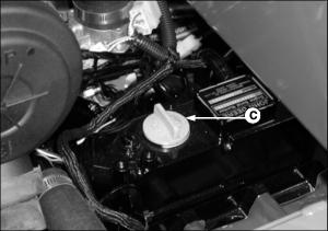
11. Remove oil fill cap (C) on top of engine.
12. Add oil to engine as follows:
· Run engine at a slow throttle speed for approximately two minutes.
· Check area under engine for oil leaks.
16. After approximately two minutes check engine oil level.
IMPORTANT: Avoid damage! Avoid dirt and other contaminants from entering the oil dipstick tube location. Clean area around dipstick before removing. |
17. Remove dipstick. Wipe with a clean cloth.
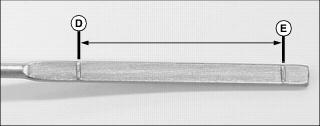
19. Remove dipstick. Check oil level. Oil should be between levels (D) and (E) on the dipstick.
· If oil is low, add oil to bring oil level no higher than level (D) on the dipstick.
· If oil is above level (D) on the dipstick, drain to proper level.
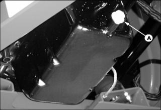
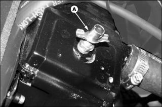
Cleaning Air Intake Screen
IMPORTANT: Avoid damage! Air intake screen must be clean to prevent the engine from overheating and to allow adequate air intake. |
1. Park machine safely. (See Parking Safely in the Safety section.)
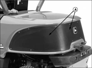
3. Clean screen (A) with a brush, compressed air or water.
Cleaning Oil Cooler and Radiator
IMPORTANT: Avoid damage! Oil cooler coils and radiator cooling fins must be clean to prevent the engine from overheating and to allow adequate air intake. |
1. Park machine safely. (See Parking Safely in the Safety section.)
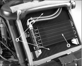
4. Remove dirt and debris from radiator (A) and oil cooler (B) using compressed air or water sprayed from the front to the rear.
5. Check oil cooler coils and radiator fins for damage.
Checking Air Filter Restriction Indicator
1. Park machine safely. (See Parking Safely in the Safety section.)
NOTE: Indicator will not function correctly if plastic indicator housing is damaged.
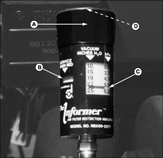
3. Check air restriction indicator (A).
· When the indicator window (B) is yellow, no air cleaner service is required.
· When the indicator window is red, air cleaner element needs replacement.
· Vacuum scale (C) on indicator shows how restricted the air cleaner elements are becoming.
4. Depress the rubber button (D) on top of the housing to reset indicator.
Servicing Air Cleaner Elements
Primary Air Cleaner Element
1. Park machine safely. (See Parking Safely in the Safety section.)
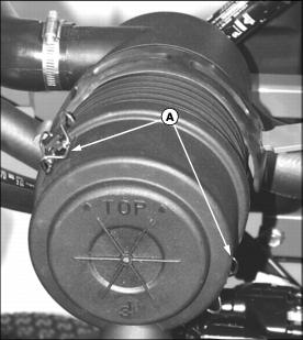
4. Release spring latches (A), and unhook latches from air cleaner housing.
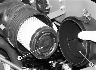
5. Remove air cleaner cover (B).
6. Remove and discard primary element (C).
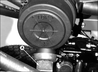
7. Install air cleaner cover, making sure the word "TOP" is facing upwards.
8. Reset air restriction indicator.
9. Start engine and run at high idle for one minute.
10. Stop engine. Check air restriction indicator:
· If indicator window remains yellow, air cleaner is ready for operation.
· If indicator window has turned red, change secondary air filter element.
Secondary Air Filter Element
2. Remove primary air cleaner element.
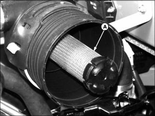
3. Remove and discard secondary element (A).
4. Install a new secondary element.
5. Install air cleaner cover, making sure the word "TOP" is facing upwards.
Cleaning Rubber Dust Unloading Valve
IMPORTANT: Avoid damage! Never operate the engine without air cleaner elements and rubber dust unloading valve installed. |
1. Park machine safely. (See Parking Safely in the Safety section.)
4. Remove dust unloading valve (A) from air cleaner housing, and clean. Replace if damaged.
5. Install dust unloading valve.
Checking Air Intake Hoses and Clamps
1. Park machine safely. (See Parking Safely in the Safety section.)
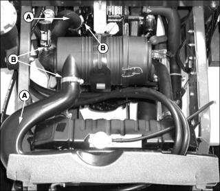
4. Check air intake hoses (A) for cracks or damage. Replace if necessary.
Service Cooling System Safely
Recommended Engine Coolant
The following John Deere coolant is preferred:
· COOL-GARD PRE-DILUTED SUMMER COOLANT (TY16036).
· COOL-GARD CONCENTRATED SUMMER COOLANT (TY16034)
If neither of the above coolants is available, use an ethylene glycol base coolant that meets the following specification:
Check container label before using to be sure it has the appropriate specifications for your machine. Use coolant with conditioner or add conditioner to coolant before using.
If using concentrate, mix approximately 50 percent antifreeze with 50 percent distilled or deionized water before adding to cooling system. This mixture will provide freeze protection to -37 degrees C (-34 degrees F).
Certain geographical areas may require lower temperature protection. See the label on your antifreeze container or consult your John Deere dealer to obtain the latest information and recommendations.
Checking Radiator Hoses and Clamps
1. Park machine safely. (See Parking Safely in the Safety section.)
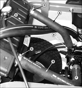
4. Check radiator hoses (A and B), and overflow hose (C) for cracks or damage. Replace if necessary.
5. Tighten hose clamps (D, E, F, and G) if needed.
Checking Coolant Level
1. Park machine safely. (See Parking Safely in the Safety section.)
2. Allow engine to cool. Open engine cover.
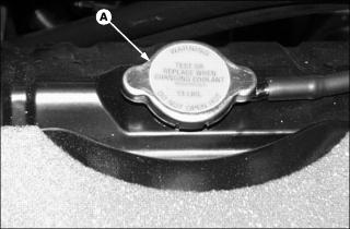
3. Slowly open and remove radiator cap (A), and check that coolant level is up to filler neck.
4. If coolant level is low, open air bleed petcock on right side of radiator, add coolant, and close air bleed.
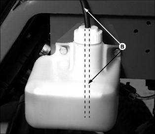
6. Check coolant recovery tank. Make sure the overflow hose (B) is not touching the bottom of the recovery tank.
7. Coolant recovery tank should be half full at engine operating temperature.
8. Add coolant if level is low.
9. Check condition of hoses and clamps. Check for leaks or loose connections.
Draining Cooling System
|
· Do not operate engine without coolant. · Do not pour coolant into the radiator when the engine is hot. |
1. Park machine safely. (See Parking Safely in the Safety section.)
3. Open and remove the engine cover.
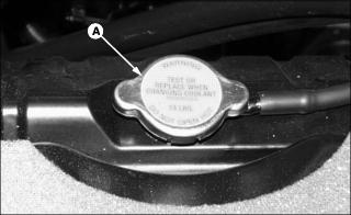
4. Slowly open radiator cap (A) to the first stop to release all pressure.
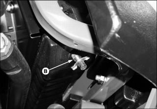
5. Open radiator drain (B) located on the bottom left side of the radiator, under rear bumper (C). Drain coolant into a pan.
6. Close petcock after all coolant has drained from the radiator.
Flushing Cooling System
1. Drain cooling system and add John Deere Cooling System Cleaner, or John Deere Cooling System Quick Flush or equivalent. Fill system with clean water. Follow directions on can.
2. Install and tighten radiator cap.
3. Start and run engine until it reaches operating temperature.
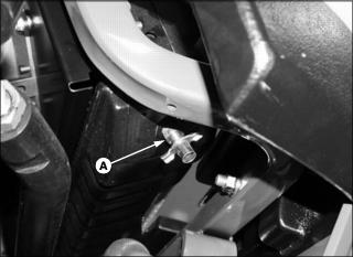
5. Open radiator drain valve (A). Drain cooling system immediately before rust and dirt settle.
6. Close radiator drain valve.
7. Fill cooling system with clean water and repeat flushing until system is clean.
8. Drain system and fill with coolant.
Filling Cooling System
1. With engine and cooling system cool, open radiator cap to the first stop to release all pressure. Press down on cap slightly and turn counterclockwise to remove.
2. Open air bleed valve (A) on top of radiator.
3. Fill cooling system until coolant drains out of air bleed valve.
· Cooling system capacity is as follows:
· Certain geographical areas may require lower temperature protection. See the label on your antifreeze container or consult your John Deere dealer to obtain the latest information and recommendations.
· John Deere Cooling System Sealer or its equivalent may be added to the radiator to seal leaks. Do not use any other additives in the cooling system.
5. Start engine and watch coolant level in radiator. Add coolant if necessary to bring coolant level up to filler neck.
6. Install and tighten radiator cap. Run engine until at operating temperature.
7. Stop engine and allow to cool down.
8. Add coolant if necessary to coolant recovery tank.
9. Check condition of hoses and clamps. Check for leaks or loose connections.
NOTE: Coolant recovery tank is used to catch overflow from radiator, and will remain about half full during operation. Coolant will flow back into radiator as needed after system cools.
Servicing Diesel Fuel Filter
NOTE: Change filter when fuel level is low.
Checking
1. Park machine safely. (See Parking Safely in the Safety section.)
4. Locate the fuel filter sediment bowl on the left side of the engine.
5. Look for water in the sediment bowl (A) indicated by the red float ring being lifted up off the bottom.
Cleaning and Replacing
1. Close fuel shut-off valve (B) by turning to the horizontal position.
2. Unscrew collar (C) to remove bowl and filter. Discard filter.
3. Clean bowl and install new filter.
4. Install bowl and collar. Tighten collar hand tight.
5. Open fuel shut-off valve by turning lever to vertical position (shown).
6. Prime fuel system using primer lever on fuel pump.
7. Start engine and check for leaks.
Servicing Gasoline Fuel Filter
NOTE: Change filter when fuel level is low.
Checking
1. Park machine safely. (See Parking Safely in the Safety section.)
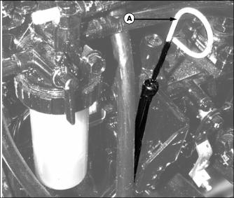
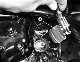
4. Locate the fuel filter (A) on the left side of the engine.
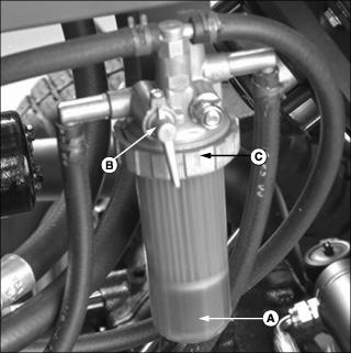
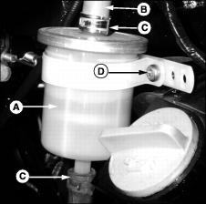
Replacing
1. Clamp the fuel hose (B) above fuel filter using locking pliers.
2. Loosen the clamps (C) on fuel hoses above and below fuel filter.
3. Pull the fuel hoses from the top and bottom fuel filter fittings.
4. Loosen the screw (D) holding the filter mounting strap to the engine block, and remove fuel filter from engine.
5. Install new fuel filter into mounting strap, making sure large end of filter is at the top.
6. Install fuel hoses onto fuel filter fittings. Secure hoses with clamps.
8. Turn key switch to run position to start electric fuel pump. Wait for filter to fill with fuel and check for leaks.
Priming Diesel Fuel System
NOTE: It may be necessary to prime the fuel system after running out of fuel or changing the fuel filter.
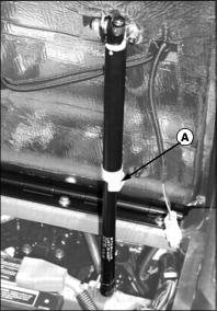
1. Locate the fuel pump (A) on lower left side of engine.
2. Pump priming lever (B) on fuel pump until fuel fills up glass bowl of fuel filter.
3. Start engine. If engine will not start, repeat priming system.
Servicing Spark Plugs (Gasoline Engine)
1. Park vehicle safely. (See Parking Safely in the Safety section.)
2. Open engine cover and raise operator's platform.
3. Clean debris from top-left side of engine in area around spark plugs.
4. Disconnect one spark plug wire at a time to avoid confusing wires at installation.
5. Pry the spark plug wire boot (A) up from the engine block using a small screwdriver.
6. Blow out the spark plug cavity with compressed air.
7. Remove and inspect the spark plug:
· Clean the spark plug and check for damage or excessive wear; replace if necessary.
· If plugs are in good condition, check gap.
8. Check and adjust spark plug gap to 0.76mm (0.030 in.)
9. Install spark plugs. Tighten to 20 N·m (15 lb-ft).
11. Repeat for other spark plugs.
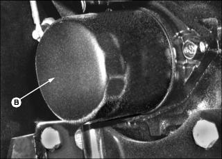
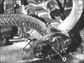
Checking and Adjusting Alternator Belt
Check Belt Tension
1. Park machine safely. (See Parking Safely in the Safety section.)
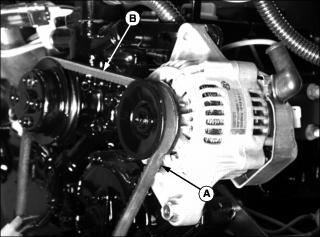
· Inspect belt for excessive wear, damage or stretching while mounted on engine.
· Apply finger pressure to the belt approximately halfway between the alternator and water pump pulleys at (B). Belt should deflect 10-15 mm (3/8 - 1/2 in.). Adjust if too tight or too loose.
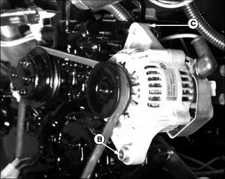
Adjusting Belt Tension
1. Loosen adjustment bolt (C).
2. Loosen alternator mounting bolt (D).
3. Apply outward pressure to the alternator housing.
4. Tighten adjustment bolt (C) and mounting bolt (D).
· Apply finger pressure to the belt approximately halfway between the alternator and water pump pulley. Belt should deflect 10-15 mm (3/8 - 1/2 in.).
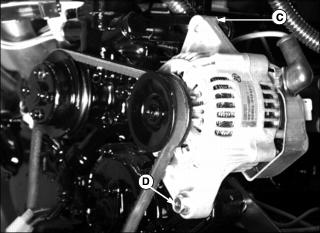
Replacing Alternator Belt
1. Park machine safely. (See Parking Safely in the Safely section.)
4. Loosen adjustment bolt (A).
5. Loosen alternator mounting bolt (B).
6. Push alternator in towards engine to loosen alternator belt tension.
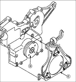
· Remove the three screws holding crankshaft sensor bracket (C) to engine.
· Pull bracket away from crankshaft pulley (D).
8. Remove the worn alternator belt from the pulleys, and pull over fan blades to remove from the machine.
NOTE: It may be necessary to remove alternator adjustment bolt to loosen belt enough for it to come off of pulleys.
9. Install new belt over fan blades and install onto engine and alternator pulleys.
10. Model 1420: Install crankshaft sensor bracket onto crankshaft pulley, and secure with three cap screws.